Search the Community
Showing results for tags 'power supply'.
Found 12 results
-
 The core element of any electronic device is the power supply. Any instability or malfunction of the power supply causes the device to malfunction or demonstrate weird behavior. In some sensitive applications, we need a dual voltage-rail power supply to prepare a high current and low noise voltage at the output. In this article/video, I introduced a low-noise AC-to-DC power supply that can handle up to 4A continuously and accept input voltages up to 35V-AC. To design this power supply, I decided to use an enhanced capacitance multiplier circuit. I paid high attention to good grounding, assigned the top layer of the PCB to the ground, and drew power planes instead of tracks to carry high currents. As a result, I could not detect any noise or ripple at the output even at the maximum output current! The PCB board has two layers and to ensure high-quality fabricated boards, I sent the Gerber files to PCBWay. I tested the board for voltage drop, current delivery, and output noise. I used Siglent SDL1020X-E DC Load and Siglent SDS2102X Plus oscilloscope to perform all tests. I’m confident that this design satisfies your needs in many applications. Schematic + PCB + Full Detail: https://www.pcbway.com/blog/technology/Low_Noise_45V_4A_Dual_Rail_Power_Supply_Using_Enhanced_Capacitance_Multiplier_8a031b5e.html Specifications Input Voltage (max): 35V-AC Output Current: 4A Continuous Output Noise/Ripple: Very Low Output Voltage: 45V-DC (maximum safe, under no load)
 -
A power supply is an essential tool on every electronics bench. The TPS54202 is a highly efficient 2A synchronous buck converter with a wide 28V input voltage range and low EMI figures, making it suitable for various applications. These features make the TPS54202 an excellent choice for building a power supply. To achieve a low noise level and ensure high performance, I implemented a variety of input and output filters, along with following several PCB design techniques. The chip operates at a switching frequency of 500KHz and is equipped with internal loop compensation. Setting up the power supply is simple—just connect the input to a step-down AC transformer (e.g., 220V to 15V) and use a multiturn potentiometer to adjust the output voltage to your desired level. For the schematic and PCB design, I utilized Altium Designer 23 and shared the project with my friends for feedback and updates using Altium-365. The fast component search engine, Octopart, proved invaluable in quickly obtaining component information and generating the Bill of Materials (BOM). To ensure high-quality fabricated boards, I sent the Gerber files to PCBWay. I tested the circuit for output noise and load step response using Siglent SDS2102X Plus oscilloscope and Siglent SDL1020X-E DC load. I am confident that this circuit will meet your requirements for a compact and efficient power supply, providing reliable performance on your electronics bench. References Schematic + PCB + Gerber: https://www.pcbway.com/blog/technology/Adjustable_Low_EMI_Switching_Power_Supply_9611437d.html [1]: TPS54202: https://octopart.com/tps54202ddct-texas+instruments-71538129?r=sp [2]: 470uF-35V: https://octopart.com/eee-fk1v471aq-panasonic-44406255?r=sp [3]: 22uH-3A: https://octopart.com/etqp5m220yfm-panasonic-24904108?r=sp [4]: 5K Potentiometer: https://octopart.com/ss34a-multicomp-18903924?r=sp [5]: SS34: https://octopart.com/ss34a-multicomp-18903924?r=sp

-
Whenever you hear the transformerless supply term, you initially imagine the capacitor-based solution, which means a high voltage capacitor in series with the mains line, then a bridge rectifier, a Zener diode, a filtering capacitor, and so on. Such a circuit is not just able to deliver sufficient current for many applications, also, it is not a reliable solution for the industry, although you might see such circuits in some cheap products that are designed to have a low cost. A month ago, I was repairing a washing machine mainboard. In the examination process, I realized that it is equipped with an LNK304 chip that is used in transformerless supplies. So I decided to design a circuit based on this chip to be used in your applications. The circuit contains 220VAC mains input protection, output filtering, and a regulator. To design the schematic and PCB, I used Altium Designer 22 and the SamacSys component libraries (Altium plugin). To get high-quality fabricated PCB boards, I sent the Gerbers to PCBWay and purchased original components using the componentsearchengine.com. To test the current handling and stability of the output voltage, I used the Siglent SDL1020X-E DC Load and examined the power supply output noise using the Siglent SDS2102X Plus oscilloscope. References main: https://www.pcbway.com/blog/technology/220Vac_to_5Vdc_Transformerless_Power_Supply_Using_LNK304_5b2e2d7d.html DB107G schematic symbol, PCB footprint, 3D model: https://componentsearchengine.com/part-view/DB107-G/Comchip%20Technology LNK304G schematic symbol, PCB footprint, 3D model: https://componentsearchengine.com/part-view/LNK304GN-TL/Power Integrations 78M05 schematic symbol, PCB footprint, 3D model: https://componentsearchengine.com/part-view/MC78M05CDTG/onsemi Electronic designing CAD software plugins: https://www.samacsys.com/library-loader-help Altium Designer plugin: https://www.samacsys.com/altium-designer-library-instructions Siglent SDL1020X-E DC load: https://siglentna.com/dc-electronic-load/sdl1000x/ Siglent SDS2102X Plus oscilloscope: https://www.siglenteu.com/digital-oscilloscopes/sds2000xp/
-
DC to DC buck converters is a famous topology in the electronic and a widely used circuit in electronic devices. A buck converter steps down the input voltage while it increases the output current. In this article/video, I have discussed a DC to DC buck converter that can be used effectively as a switching power supply. The output voltage and current are adjustable: 1.25V to 30V and 10mA to 6A (continuous). The power supply supports the constant voltage (CV) and constant current (CC) features. Two LEDs demonstrate the CV and CC status. The circuit is compact and both sides of the PCB have been used to mount the components. To design the schematic and PCB, I used Altium Designer 21, also the SamacSys component libraries (Altium plugin) to install the missing schematic symbols/PCB footprints. To get high-quality fabricated PCB boards, I sent the Gerbers to PCBWay. To test the circuit, I used the power analysis feature of the Siglent SDS2102X Plus oscilloscope (or SDS1104X-E), Siglent SDL1020X-E DC Load, and Siglent SDM3045X multimeter. Isn’t cool, so let’s get started! Specifications Input Voltage: 8V to 35VDC Output Voltage: 1.25V to 32VDC Output Current (continuous): 10mA to 6A Output Current (short period): 7A to 8A Output Noise (no load): 6mVrms (9mVp-p) Output Noise (6A load): 7mVrms (85mVp-p) Output Noise (6A load, 16P-average): 50mVp-p Efficiency: up to 96% References Source: https://www.pcbway.com/blog/technology/0_30V__0_7A_Adjustable_Switching_Power_Supply.html [1]: XL4016 datasheet: http://www.xlsemi.com/datasheet/xl4016%20datasheet.pdf [2]: MBR20100 datasheet: https://www.diodes.com/assets/Datasheets/MBR20100C.pdf [3]: TS4264 datasheet: https://www.mouser.com/datasheet/2/395/TS4264_D15-1142598.pdf [4]: MCP6002 datasheet: https://componentsearchengine.com/Datasheets/2/MCP6002T-I_SN.pdf [5]: Altium Designer: https://www.altium.com/yt/myvanitar [6]: SamacSys Altium plugin: https://www.samacsys.com/altium-designer-library-instructions [7]: Supported SamacSys plugins: https://www.samacsys.com/pcb-part-libraries [8]: XL4016 schematic symbol, PCB footprint, 3D model: https://componentsearchengine.com/part-view/XL4016/XLSEMI [9]: MCP6002 schematic symbol, PCB footprint, 3D model: https://componentsearchengine.com/search?term=mcp6002 [10]: TS4264 schematic symbol, PCB footprint, 3D model: https://componentsearchengine.com/part-view/TS4264CW50%20RPG/Taiwan%20Semiconductor [11]: MBR20100 schematic symbols, PCb footprint, 3D model: https://componentsearchengine.com/part-view/MBR20100CT-G1/Diodes%20Inc. [12]: Siglent SDS2102X Plus oscilloscope: https://siglentna.com/digital-oscilloscopes/sds2000xp/ [13]: Siglent SDS1104X-E oscilloscope: https://siglentna.com/digital-oscilloscopes/sds1000x-e-series-super-phosphor-oscilloscopes/ [14]: Siglent SDL2010X-E DC Load: https://siglentna.com/dc-electronic-load/sdl1000x/ [15]: Siglent SDM3045X Multimeter: https://siglentna.com/digital-multimeters/sdm3045x-digital-multimeter/
-
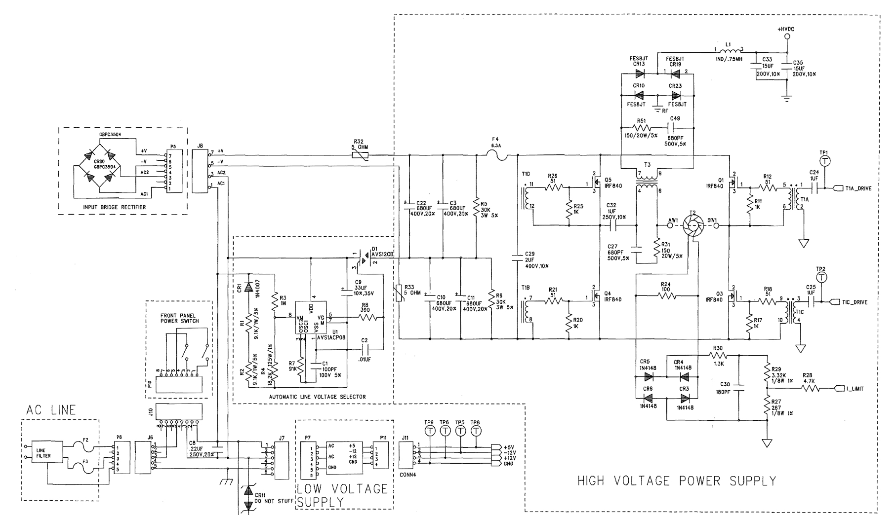
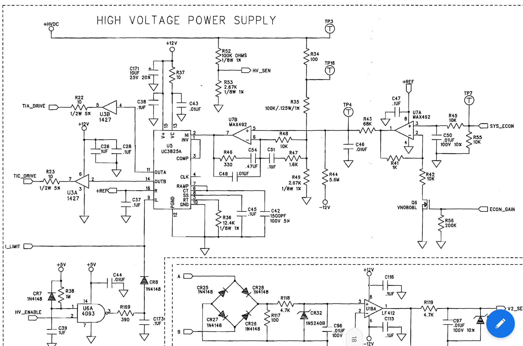
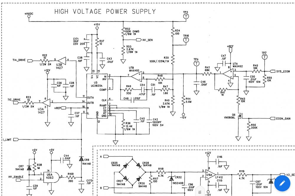
Hello I am trying to repair a smps power supply based on UC3825A Problem is the resistor R49 & R34 get burst as soon as i start the smps I am not able to find out the issue SYS_ECON is a 0-5v given from MCU desired by user to control 0-180v smps output

-
Features: AC – DC Conversion Double output voltages (Positive – Ground – Negative) Adjustable positive and negative rails Just a Single-Output AC transformer Output noise (20MHz-BWL, no load): Around 1.12mVpp Low noise and stable outputs (ideal to power Opamps) Output Voltage: +/-1.25V to +/-25V Maximum output current: 300mA to 500mA Cheap and easy to solder (all component packages are DIP) A double output low noise power supply is an essential tool for any electronics enthusiast. There are many circumstances that a double-output power supply is necessary such as designing pre-amplifiers and powering OPAMPs. In this article, we are going to build a linear power supply that a user can adjust its positive and negative rails independently. Moreover, just an ordinary single-output AC transformer is used at the input. References Source: https://www.pcbway.com/blog/technology/Low_Noise_Adjustable_Linear_AC_DC_Power_Supply.html [1] LM317 Datasheet: http://www.ti.com/lit/ds/slvs044x/slvs044x.pdf [2] LM337 Datasheet: http://www.ti.com/lit/ds/symlink/lm137.pdf [3]: Schematic Symbol and PCB Footprint for LM317: https://componentsearchengine.com/part.php?partID=248007 [4]: Schematic Symbol and PCB Footprint for LM337: https://componentsearchengine.com/part.php?partID=290650 [5]: Altium Plugin: https://www.samacsys.com/altium-designer-library-instructions
-
 Dont mean to resurrect a dead horse but I recently came across the old stabilized o-30 volt power supply. I found the original magazine article from 1978. Seems like it lost it's original design over the years. I attached the pdf of the issue. It starts on page 40. Practical-Electronics-1978-10.pdf
 -
hello, i found out your page on internet http://www.electronics-lab.com/400v-5a-power-supply-brushless-motor-drivers/ 400V - 5A Power Supply For Brushless Motor Drivers - Electronics-Lab Although the power supply design is specific to the Brushless Servo Drivers mainly for IPM Modules, the concepts and circuit design may be used for any power supply requires high voltage output up to 400V DC and 5 Amps. The power supply is an unregulated design with an option to allow connection to ... www.electronics-lab.com however i have several questions about this board: -how does this board is working?can i connect a arduino UNO on it to manage the set up? -how does it coast? -is it abble to supply a bdlc motor direct drive of 600 watt? (0,6 hp) if yes,how do we manage the rpm on this board? i use a arduino uno to pilote a board i made by my own,this board is composed of 6 IRF840 and 3 microcontrollers IR2104 meanly,i found out the software on internet to this page https://simple-circuit.com/arduino-sensorless-bldc-motor-controller-esc/ but am not sure neither that the code can be efficient enough to supply the kind of motor i use.. thanks to care regards from france nicolas rollet Sensorless BLDC motor control with Arduino - Simple Projects This topic shows how to build a sensorless brushless DC (BLDC) motor controller or simply an ESC (Electronic Speed Controller) using Arduino. There are two types of brushless DC motors: sensored and sensorless. Sensorless BLDC motor commutation is based on the BEMF produced in the stator windings. simple-circuit.com
-
How i can build transformer less circuit for 10 Volt 1000 Ampere Power supply.
-
 This article is automatically translated by google translate, just for reference.Chinese version PDF please CLICK HERE.Low voltage DC powerPart 3: Electromagnetic compatibility(EMC)GB This section 21560 specifies the power level does not exceed 30 kW,an input AC or DC input voltage is not more than 660 V,the DC output voltage does not exceed 250 V power source of various means(PSU)of the electromagnetic compatibility(EMC)requirements.Power supply means operate independently, or other devices installed in adequate electrical and mechanical protection are -for some special industrial applications (e.g. chemical and metallurgical) power supply apparatus used, there may be other products EMC standards. At this time, perform this section may also perform those products EMC standards ^many of the power supply apparatus is as relating to different EMC used part of a large apparatus standards, following a) and b)show power classification and EMC scope standards. A detailed breakdown of the power supply, see Appendix A.Expected power (a separate instrument)independentThis section applies to the power supply means as a unit and having a direct function of development, especially in a separate unit on the market"Component supply be divided into two operation:the power supply member regarded as of the instrumentPresent part deemed suitable instrument (e.g., intended for the facility or sold to the public) part of the power supply device,which EMC by the instrument equirements considered for use without additional prepended EMC tests. this does not include a maintenance spares sales the power supply device, which has been carried out as a member of the test machine"Is intended for professional assembly / installer component supplysection applicable to this kind of power, but help to meet different standards for the relevant end product EMC requirements. such parts supply is expected. these products may be sold by the end of tantalum professional installation personnel who install terminal products to professional assemblers, or delivered to wholesale markets. in both cases, the user of the end product is not only to fulfill its own responsibilities. after assembly further assumed that EMC testsNote:the power supply device member people end product, emission value Can be changed (e.g. due to changes in the ground conditions).Purpose of this section is to define the power supply EMC and test methods for limits device,comprising one thousand possible interference to other electronic devices (e.g., a radio receiver, a measuring device and a computer apparatus) electromagnetic emission limits, and a continuous, transient conduction disturbance and radiated disturbances (including electrostatic discharge) immunity electromagnetic limits.this part of the predetermined minimum power supply device EMC requirements.comply with this section, no require additional EMC tests, nor beyond the portion of the necessary.2 normative documentsReferences the following are incorporated by GB reference in this section 21560, constitute provisions of this section. dated references, which then All amendments (not including errata content) or revisions do not apply to this section, however, encouraged to whether the latest versions of these documents are part of the parties to this agreement. undated references, the latest version applies to this 2900. 33-2004GB / T part.term Electrical power Electronics 60050- (IEC 551: 1998 and IEC 60050-551- 20: 2001, IDT)D 2900. The term electromagnetic Electrotechnical 60-2002(eqvIEC 60050-121: 1998) GB / T semiconductor converter of basic requirements(eqvIEC 60146-1-1: 1991) GB 4343. 1 electromagnetic compatibility appliances, electric tools and similar apparatus Part 1: Emission (CISPR 14 ~ 1: 2000,term & Electrotechnical electromagnetic compatibility (IEC 60050-161: 1990, IDT)industrial, scientific and medical(ISM)radio disturbance characteristics limits apparatus and methods of measurement(CISPR 11: 20〇3,16113.1-GB / T DT)1995 radio disturbance and immunity measuring apparatus specificationsGB 9254, -1998 limits and methods of measurement harassment radio information technology equipment(IDTCISPR 22: 1997) GB / T General Requirements 1 and 2000 detects a calibration laboratories(IDT ISO / IEC 17025: 1999)GB/ T 16935.1-1997 with the insulating first part of low-voltage systems: principles, requirements and tests(IDTIEC 60664-1: 1992) GB / T low voltage DC power supply of the performance apparatus to be (IEC 61204: 2001, MOD)electromagnetic compatibility limits for harmonic current emissions (equipment input current<16 a) (IEC 61000-3-2:electromagnetic compatibility limit of having a rated current 16 a voltage the device= in the low-voltage supply system fluctuations and flicker in limit(idtIEC 61000-3-3: 1994) GB / T electromagnetic compatibility test and measurement techniques electrostatic discharge immunity test(IDTIEC 61000-4- 2:. 1995) GB electromagnetic compatibility test and measurement techniques RFEMS Test(idt 1 EC 61000-4-3: 1995)electromagnetic test and measurement techniques compatible with fast transient electrical pulses immunity test CianIEC 61000-4-4-.1995) GB / T electromagnetic compatibility testing and measurement techniques surge (impact) immunity test( idt IECS 1000-4- 5: 1995) GB /test the electromagnetic compatibility and radio frequency field measurement techniques conducted disturbances, induced immunity(IDTIEC 61000-4-6! 1996) GB / T Electromagnetic compatibility Testing and measurement techniques - Voltage dips, short interruptions and voltage variations immunitytests(idt 61000-4-11: 1994)IEC60〇5 IEC-131 billion International Electrotechnical dictionary(IEV)Part 131: Circuit theory60050-151 IEC International Electrotechnical dictionary(IEV)Zi section 151: electrical device and a magnetic device3 and the terms definedGB / T 2900.33. GB / T /,/ T 3859.1 GBand IEC60050-151 is defined given as well as the following definitions apply to this section.Tambient environment1. 1residential environments residential environmentis directly connected to all domestic low-voltage power supply utility facilities. Protection from 10 ni,about the size of the room.3.1 + 2commercial and light industrial environment, commercial and light industrial environmentare not necessarily all connected to a common low-voltage power supply and light industry commercial facilities. The desired status broadcast radio and television receivers use, protection the distance of 10can be m or 30 m.1.3Industrial environment industrial environmentis not directly connected to a common low-voltage power supply of industrial facilities, large houses due PROTECTION distance 30 m.3.2protection zone protection distancefrom the electronic or electrical devices. Within this distance, the interference level should not affect the use, such as broadcast radio and other electronic or electrical device such as a television receiver.3.3Distribution System distributed power systemby the power distribution bus to supply power to a fixed power converter system.3.4port portProduct-specific interfacewith an external electromagnetic environment.Examples of ports:input cross Su port DC input«U the ground port13.4.port of the housing enclosore portPhysical interface power supply device products. Emitting an electromagnetic field through which the mount of the power supply device or invasion by products.3.4.2signal or control line port signal or control line portprovides diagnostic or low power level control information is input or output port.3.4.3DC input port dc * input power portconnected to external DC power supply port.3.4.4DC output port dc Output power portDC power output port connected to the outside.3.4.5AC input port Sapporo c. Input power portterminal connected to external AC power supply U.3.5Power(device)power supply; PSUthe input electrical energy into one or more output power of the electric or electronic device.3-5.1Power member component power supplya modular power supply device modular PSU The power supply device sub-unit sub-unit PSUfor providing or changing the electrical energy from the electrical means and / or the electronic device thereof. They are not expected to operate independently, by a professional assembly / installation personnel charged with the end product.Read more... GBT-21560-3-2008-Low-voltage-power-supplies-DC-output-Part-3-Electromagnetic-compatibility(EMC).pdf
 -
 Hi, I've been working on replacing the two 10k potentiometers for voltage and current control with two rotary encoders. The idea is to get (theoretically) arbitrarily fine control via software on an ATMega328P microcontroller. The microcontroller would also be in charge of outputting desired and measured voltage and current values to an LCD. Since I haven't found any suitable digital potentiometers I figured I'd simply generate the analog voltages for the non-inverting inputs of U2 and U3. U2 gets a voltage between 0 and 10V using the uC's PWM output, a low pass filter and an op amp. Points 5 and 10 are connected with a 10k resistor. This part is working brilliantly so far. However current limit control is giving me some trouble. Again points 6 and 11 are connected with a 10k resistor and the non-inverting input of U3 is fed with an analog voltage between 0 and 1.4V (again via PWM and low pass filter). To test the setup I shorted the outputs of the supply with my multimeter, turned up the voltage to about 10V and then slowly increased the current limit. Seemingly at random one of the following scenarios occurs: The current limit increases way too fast (the microcontroller sends the signal for .5A but the multimeter already reads 3A) The current limit increases fairly accurately as it should. The current limit gets stuck and then goes haywire at some 16A and Q4 lets the magic smoke out. Am I wrong in thinking I could generate U3's input voltage isolated from points 6 and 11? If I'm not just being stupid somewhere else my suspicion is that my approach kills some vital feedback path... I'd appreciate any input, thanks!
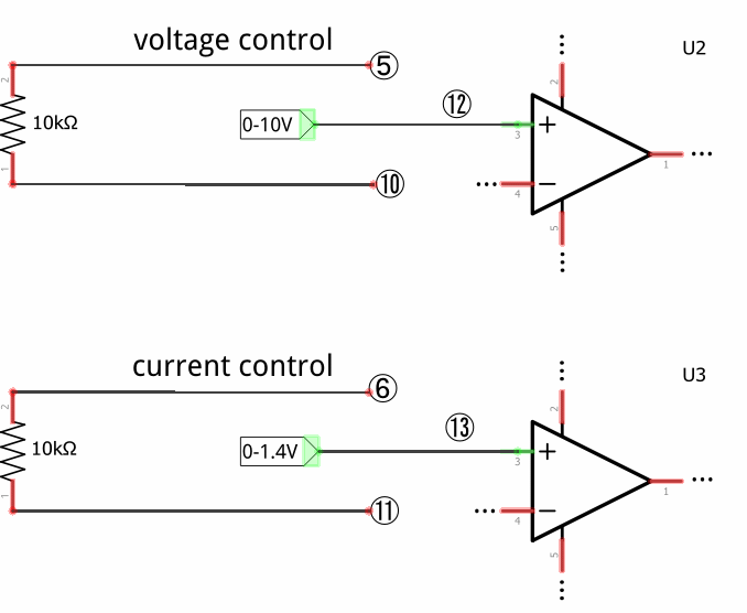
-
with PCB and Simulation Power Supply 1.2~30VDC, 1.5A.rar