New Stompbox Project

SparkyCal

Mar 11, 2020
863
Joined
Mar 11, 2020
Messages
863
So, I have decided to try another guitar pedal project, but first. I have a few questions:

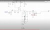
I decided I will use the attached schematic as my template. What I mean is that I will use this schematic as my starting point, but I will be making changes to it- hence my questions:

I recognize that when using an Op Amp, it is important to know the pin mappings, because not all of them has the same configuration. I also know one has to be cognizant of single vs dual op amps.

Let's assume I want to try a few different op amps in the schematic referenced in the attached picture. I will make sure that I make the necessary chnages in order to make sure the pin mappings are correctly wired up to.

In the schematic, the + input of the op amp, receives its biasing from the lead coming from R41 (the 1M resistor). That voltage coming from there is roughly half of 9 volts, which is 4.5 volts

Can I assume that this voltage (the 4.5 volts ), will work with the different op amps I use. Specifically, I have the following op amps:

UA741
J4558D
LF353N

I guess what I am wondering about, is whether I have to worry about the bias voltage going into the + input of the op amp, or can I assume that the 4.5 volts will work with each op amp?

Thank-you
 

Attachments

  • Screen Shot 2020-06-22 at 10.21.12 PM-4.jpg
    Screen Shot 2020-06-22 at 10.21.12 PM-4.jpg
    122.3 KB · Views: 13

SparkyCal

Mar 11, 2020
863
Joined
Mar 11, 2020
Messages
863
hmmm. I noticed that the LF353N op amp has a Power Supply Voltage (VCC) of 18volts

I assume its Pin 8 will need 18volts, but how do i know what the + Input requires in terms of its biasing?

Can someone tell me where in it data sheet, I can find that out? Here is the datasheet.
https://www.ti.com/lit/ds/symlink/lf353-n.pdf

I also noticed that the datasheet says Input Voltage range + or -15V. Does this mean that the chip 's + input (pin 3), could be properly biased as long as the voltage does not exceed 15volts? In other words, will the 4.5 volts work?
 
Last edited:

Harald Kapp

Moderator
Moderator
Nov 17, 2011
14,273
Joined
Nov 17, 2011
Messages
14,273
The UA741 has a minimum operating voltage of +- 5 V, meaning + 5 V at V+, -5 V at V- a total of 10 V between V+ and V. It will not operate reliably from a 9 V battery.
I can't find a datasheet for a J4558D opamp, but I find RC4558. This one also is rated for +-5 V operation and will not work reliably from 9 V.
For the LF353N I can't find a min. rating for the operating voltage. However, when operated from +-15 V, the output swing is +-12 V minimum. In other words V+-2V to V- +3 V.With a 9 V battery that means output is limited to (9 V-3V) ... (0V+3V) which gives you 3V...6V. May be good enough in zjis application, needs to be tested.

I assume its Pin 8 will need 18volts, but how do i know what the + Input requires in terms of its biasing?
It is fairly common for opamps, especially but not limited to older ones, to have a so called dual supply: one positive and one negative with 0V being in the middle of it. What the circuit you use does is: it operates the opamp from a single supply voltage (0V ... +9V). Since the AC signal from the input and at the output needs to swing between positive and negative, centered around 0 V, this opamp (as any amplifier) can be used with a single supply voltage only by using a trick. The amplifier is offset by 1/2 Vcc (4.5 V via R41), such that 1/2 Vcc is a virtual ground for the AC signal. Capacitor C23 at the input adds the AC input signal on top of the offset such that an input signal of e.g. AC +-100mV leads to an an effective input of 4.4 V ... 4.6 V at the opamp's input.
C3 at the output removes this DC offset.
Have a look at this detailed article for more information.

I will use this schematic as my starting point, but I will be making changes to it
It is probably not wort experimenting with the opamp. Most reasonable opamps will easily handle signals in the audio frequency range fairly well. The effect comes from the distortion introduced by the diodes in the feedback path, adjustable by the 500kΩ gain potentiometer. To achieve a variety of effects it is imho much more useful to experiment with the feedback loop, e.g. using different types of diodes, diode connected transistors instead of diodes, other non-linear or frequency dependent componnets or a combination of them etc.
 

Alec_t

Jul 7, 2015
3,817
Joined
Jul 7, 2015
Messages
3,817
If you are only ever going to be using a single 9V battery as the power supply it would be preferable to use op-amps which have a 'rail-to-rail' common-mode input range (to make input biassing less critical) and a rated single supply voltage range which includes 9V.
 

SparkyCal

Mar 11, 2020
863
Joined
Mar 11, 2020
Messages
863
Great advice Harald and Alec. Thank you. I have been away on vacation and I had forgotten that it is the diodes that are worth tinkering with to get different distortion flavours. I used to know that. Thanks for reminding me. I guess my question is, if I want to continue to use those particular op amps, how do I power them to ensure they get what they need. Is it a question of using a 9 volt adapter plugged into a wall, or is it a question of using a more powerful battery or batteries in series? I am a little confused because most pedals I buy ( boss, Fulton) etc, use 9 volt batteries or adapters.
 

Harald Kapp

Moderator
Moderator
Nov 17, 2011
14,273
Joined
Nov 17, 2011
Messages
14,273
As your original circuit works from a single 9 V battery, there is no need to change that.
 

bertus

Moderator
Nov 8, 2019
3,837
Joined
Nov 8, 2019
Messages
3,837
Hello,

Here is a list with opamps that are rail-to-rail in and out.
There are even opamps that work under 5 volts.

Bertus
 

Attachments

  • Operational_Amplifiers_Rail_to_Rail_Input.pdf
    20.6 KB · Views: 1

Harald Kapp

Moderator
Moderator
Nov 17, 2011
14,273
Joined
Nov 17, 2011
Messages
14,273
While a rail-to-rail opamp is a good choice for low supply voltage applications, it is imho not required here.
With a 9 V power supply and a 3V guard band from the output to the supply rails, the output of the opamp can swing between 3 V ... 6 V cf. post #3). After removing the DC offset with the output capacitor, that leaves us with a +-1.5 V peak AC signal which is equivalent to 1.06 V RMS.
This is afaik good enough for a stomp box. Line signal levels are typically between 0.32 V (consumer) and 1,23 V (professional), see e.g. this source.
The above calculation is worst case acc. to the datasheet. Probably a real opamp is better than that, resulting in an even higher RMS output signal.
 

Audioguru

Sep 24, 2016
3,656
Joined
Sep 24, 2016
Messages
3,656
The extremely old (52 years) uA741 opamp is too noisy (hiss) and the 4558 dual opamp have a minimum input resistance of only 300k. Electric guitar pickups need the extremely high input resistance of a vacuum tube or Jfet input opamp.

The LF353 and TL081 opamps have Jfet inputs but are also too noisy (hiss) and need a supply at least 10V but a 9V battery drops to 6V. They do not need 18V, instead their Maximum Allowed Supply is plus and minus 18V which is 36V.

Instead, use a modern OPA134 single or OPA2134 dual audio opamp that have Jfet inputs, are low noise and operate from a supply down to 5V.

C3 in the circuit has its polarity backwards and the tone control circuit is bad since it overloads the opamp output with 22nF when the tone control is turned up causing very high frequency oscillation which might burn out the opamp and/or battery.
 

SparkyCal

Mar 11, 2020
863
Joined
Mar 11, 2020
Messages
863
Hi guys . Bear with me as I am trying to push myself to learn a particular aspect this time around. Here is what i want to learn:

I want to learn more about reading data sheets.

I know each Op amp requires a certain amount of bias current or voltage at its + pin (usually pin 3)

Questions

1. Is it current or voltage that is required at pin 3?

2. What heading, or where on the data sheet is this value displayed?

thank you for all the other info. I have been reading it. Bertus....nice to see you as well.
 

SparkyCal

Mar 11, 2020
863
Joined
Mar 11, 2020
Messages
863
I have a feeling it’s this


Input Bias Current: The current that flows into the input pins to bias the transistors (about 80nA in this case). Note: Some FET op-amps have input bias currents well below 1pA.


I got This from a data sheet explanation for a particular op amp

if this is true, what is the relationship between the voltage divider circuit that produces the biasing, and the input bias current. In other words, how do I figure out how to build a voltage divider circuit that satisfies the input bias current requirement for a particular op amp.

can we use the LF353 as an example please

thank you
 

bertus

Moderator
Nov 8, 2019
3,837
Joined
Nov 8, 2019
Messages
3,837
Hello,

Have a look at the attched PDF's about single supply opamp circuits.

Bertus
 

Attachments

  • sloa058 A Single-Supply Op-Amp Circuit Collection.pdf
    163.1 KB · Views: 4
  • slyt189 Single-supply op amp design.pdf
    244.1 KB · Views: 0

Harald Kapp

Moderator
Moderator
Nov 17, 2011
14,273
Joined
Nov 17, 2011
Messages
14,273
I know each Op amp requires a certain amount of bias current or voltage at its + pin (usually pin 3)
No it doesn't. Only when used with a unipolar power supply.

nput Bias Current: The current that flows into the input pins to bias the transistors
Right. In an ideal opamp this current is negligible. In a real opamp, one strives to have it as low as possible, but there are means to compensate for it.

if this is true, what is the relationship between the voltage divider circuit that produces the biasing, and the input bias current. In other words, how do I figure out how to build a voltage divider circuit that satisfies the input bias current requirement for a particular op amp.
The bias current changes the divider ratio of the voltage divider by a small amount. As long as the current through the voltage divider is large compared to the bias current, this is not a notable issue. Set the current through the voltage divider to e.g. > 100 × Ibias and you'll be good.
The LF353 has a typical input bias current of 50 pA (!) - up to 8 nA max. in the worst case. Assuming 8 nA, the above estimation gives a ballpark figure for the current through the divider of > 800 nA (note: this is really an esimate, no fixed rule). 9 V supply voltage and 800 nA result in a total resistance of the divider of 9 V / 800 nA = 11.25 MΩ. This is insensibly high, way too sensitive to noise. A sensible choice is a much smaller value of e.g. 200 kΩ, 2 × kΩ in series for a divider ratio of 1/2.
9 V / 200 kΩ = 45 µA, much more than the minimum of 0.8 µA (800 nA), The bias current of 8 nA will not have a noticeable influence on the divider: 8 nA / 45 µA = 0.018 % -> the tolerance of a quality 1 % resistor pair will have more influence on the divider ration than the bias current.

I understand you're looking for hard rules, mathematical equations etc, but in this case you're out of luck. It takes some experience and a "feeling" for what is going on to achieve useful results.
47 kΩ resistors or 220 kΩ resistors or anything in this admittedly big ballpark will work equally well.


Note that the absolute value of the bias voltage (1/2 × VCC is not important in this application. The circuit will work equally well with a bias voltage of 4 V or 5 V. This bias voltage is there to have a virtual ground for the AC signal. It is common practice to put this bias voltage in the middle of the supply voltage range to allow for maximum modulation of the AC signal. To achieve possibly interesting effects you may experiment with a bias voltage near 0 V or near 9 V. This will lead to the signal being clipped for low voltages or high voltages only - might sound interesting.
 

Audioguru

Sep 24, 2016
3,656
Joined
Sep 24, 2016
Messages
3,656
An electric guitar needs a very high load resistance to sound like it is playing into an old vacuum tubes amplifier.
A pair of 200k bias resistors have values that are Much Too Low. Instead use a vacuum tube amplifier or an opamp with Jfet inputs and a high value input resistors or like in this preamp for an electric guitar:
 

Attachments

  • guitar preamp.PNG
    guitar preamp.PNG
    15.4 KB · Views: 4

Harald Kapp

Moderator
Moderator
Nov 17, 2011
14,273
Joined
Nov 17, 2011
Messages
14,273
I wasn't aware of the requirements of the driving pickup, sorry.
If you're going to stick with the opamp circuit, using 3 MΩ resistors for the voltage divider, or even 4.7 MΩ resistors will still be fine.
 

SparkyCal

Mar 11, 2020
863
Joined
Mar 11, 2020
Messages
863
Thanks again for taking the time to provide links and to explain these concepts to a newbie. I appreciate it.

Presently, I have the following circuit built as my power source of the LF353. (see attached). Do you think it will suffice?
 

Attachments

  • Screen Shot 2020-09-08 at 1.38.18 PM.png
    Screen Shot 2020-09-08 at 1.38.18 PM.png
    64.9 KB · Views: 7

SparkyCal

Mar 11, 2020
863
Joined
Mar 11, 2020
Messages
863
s
I wasn't aware of the requirements of the driving pickup, sorry.
If you're going to stick with the opamp circuit, using 3 MΩ resistors for the voltage divider, or even 4.7 MΩ resistors will still be fine.
So I should replace R 8 and R9 in the pic I just posted, with two 3M resistors?
 

Alec_t

Jul 7, 2015
3,817
Joined
Jul 7, 2015
Messages
3,817
I second AG's suggestion of using a jfet preamp. That will ensure the loading on the guitar pickup will be largely unaffected by tinkering with a subsequent circuit stage.
 
Top