help with IR2110 chips

Maglatron

Jul 12, 2023
2,025
Joined
Jul 12, 2023
Messages
2,025
Hello,

55 VDC will generate a sinus of about 39 VAC.
You need to apply the 0.707 factor to find the effective AC voltage.

Bertus
ok then would the 1:4.2 step up transformer still produce 230vac?
 

Maglatron

Jul 12, 2023
2,025
Joined
Jul 12, 2023
Messages
2,025
so 39 * 4.2 equals 156vac
156 * 0.707 give 110vac
correct? or not
 
Last edited:

bertus

Moderator
Nov 8, 2019
3,836
Joined
Nov 8, 2019
Messages
3,836
Hello,

No, You will get the 156 VAC.
You already used the 0.707 on the 55 Volts.

Bertus
 

Maglatron

Jul 12, 2023
2,025
Joined
Jul 12, 2023
Messages
2,025
MR Bertus
cool did you get what I meant when I said that the that the potential in the capacitors would collapse a moment after attaching the transformer to the circuit? because apart from the primary coil's resistance it's basically a short! what are your thoughts on this please?
also delta prime said something about the caps not depleting due to short because of the flux in the core,
so say I have my 55vac of which only 39vac is mainly used and I want rms 240vac what will be the transformer ratio please?
 

Maglatron

Jul 12, 2023
2,025
Joined
Jul 12, 2023
Messages
2,025
and also where can I buy one of the transformers at 5.8:1 ratio please?
 

bertus

Moderator
Nov 8, 2019
3,836
Joined
Nov 8, 2019
Messages
3,836
Hello,

A transformer that goes from 230 Volts to 39 or 40 Volts will do.
Connecting it in reverse will work.

Bertus
 

Maglatron

Jul 12, 2023
2,025
Joined
Jul 12, 2023
Messages
2,025
yes I get that! can you recommend where to get one?? thanks having trouble finding one!
 

Maglatron

Jul 12, 2023
2,025
Joined
Jul 12, 2023
Messages
2,025
Mr Bertus
so back to that question. if I connect the 55v to the inverter which has 50usec dead time and so it's basically on all the time and then put the output of the inverter throgh the transformer that I have, will the caps deplete very quickly because the coil on the primary has a low resistance and the voltage built up in the capacitor bank will collapse quickly coming to a resting voltage, because the primary is essentially a short? or is what Delta Prime said about the changing flux in the core of the transformer resist current and the voltage stays roughly the same? I hope you understand the question
 

bertus

Moderator
Nov 8, 2019
3,836
Joined
Nov 8, 2019
Messages
3,836
Hello,

You keep talking about a capacitor. What is the capacity and what is powering the capacitor?
A schematic would also help.

Bertus
 

Maglatron

Jul 12, 2023
2,025
Joined
Jul 12, 2023
Messages
2,025
there are four coils on the machine that I have made all have there own ac voltage, I put them through a bridge rectifier and put a 16000uF capacitor bank across the output and it's rated at 100volts in the image below is the setup of the coil and magnet arrangment the wheel spins at 550RPM so revs/sec equals 5.2 revs/sec and there are eight magnets either side alternating north south north south so from peak to peak there are 4 per revolution so 5.2 * 4 equals 36.7Hz. the voltage builds in the capacitor bank to 55v, my question is will the capacitor bank deplete when put through the IR2110 H-bridge and transformer or will the voltage stay at 55v? Thanks

ok I'll take photos later and then I'll be able to show you the machine cap bank rectifier
Hello,

You keep talking about a capacitor. What is the capacity and what is powering the capacitor?
A schematic would also help.

Bertus
 

Attachments

  • wheel.png
    wheel.png
    116.4 KB · Views: 4
  • capacitor equation.png
    capacitor equation.png
    114.2 KB · Views: 3

Maglatron

Jul 12, 2023
2,025
Joined
Jul 12, 2023
Messages
2,025
I'm taking readings of the raw ac out put for each of the coils later today and am going to try build the circuit as accurate as possible to the machine
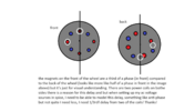
funny you should say that I've just been trying to mess about with spice, I don't know how to model my machine, so first step, going to take measurments of the coils raw ac put them through the rectifier (in spice) and set the frequency and put in the capacitor bank, so that's the plan for the minute, and make the spice simulation as close to the the real thing as possible, thanks though! what I do know is that the magnets pass the coils on one side of the wheel and the magnets on the other side of the wheel are 1/3rd out of phase and need to be able to model this the white circles represent the coils!
 

Attachments

  • wheel.png
    wheel.png
    116.4 KB · Views: 2
Top