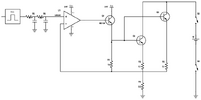
Current monitor/sensor

denci

Apr 30, 2012
86
Joined
Apr 30, 2012
Messages
86
audioguru said:
No. An emitter resistor is not needed for only one output transistor.
Are you discharging a 12V battery? My circuit with an NPN driver transistor and NPN output transistor is a battery charger, not a discharger.
what is your suggestion?
 

Hero999

Oct 28, 2007
2,433
Joined
Oct 28, 2007
Messages
2,433
The easiest way to do that is to have two circuits: one to charge the battery and another to discharge it.

A single pole RC filter is not enough to convert PWM to a steady DC voltage. You need to use two poles or more to get the voltage anywhere near smooth.


denci

Apr 30, 2012
86
Joined
Apr 30, 2012
Messages
86
I want to use circuit above but instead of supply on power transistor there is battery which discharges, for charge it we use power supply voltage, so different orientation of circuit.
Is there any calculation for additional RC pole, in my current circuit remains some ripple with one single rc pole (470E + 1u capacitor).
I have to see in my program for frequency I forget it.


Hero999

Oct 28, 2007
2,433
Joined
Oct 28, 2007
Messages
2,433
http://www.allegromicro.com/en/Design-Center/Technical-Documents/Hall-Effect-Sensor-IC-Publications/Method-for-Converting-a-PWM-Output-to-an-Analog-Output-When-Using-Hall-Effect-Sensor-ICs.aspx
http://www.cnblogs.com/shangdawei/p/3312084.html
http://www.avr-asm-tutorial.net/avr_en/AVR_ADC500.html


denci

Apr 30, 2012
86
Joined
Apr 30, 2012
Messages
86
audioguru said:
No. An emitter resistor is not needed for only one output transistor.
Are you discharging a 12V battery? My circuit with an NPN driver transistor and NPN output transistor is a battery charger, not a discharger.
sorry but I will very grateful if you give me advice about discharge circuit, I know that my version will wok but probably you have some critical comment, you have more experience!
 

denci

Apr 30, 2012
86
Joined
Apr 30, 2012
Messages
86
No. An emitter resistor is not needed for only one output transistor.

Are you discharging a 12V battery? My circuit with an NPN driver transistor and NPN output transistor is a battery

charger, not a discharger.
So, what is difference between charger and discharger, my idea was in switching relays which reconnect lines and provide both orientation??

What do you think about that?


audioguru2

Apr 6, 2004
12,026
Joined
Apr 6, 2004
Messages
12,026
This thread has been for such a long time that most schematics are gone. I do not know what you want to do.

A charger puts current into a battery from a voltage higher than the battery voltage. The current is limited or regulated.

A battery is discharged by a load that draws current out of the battery. The load current is limited.


denci

Apr 30, 2012
86
Joined
Apr 30, 2012
Messages
86
This thread has been for such a long time that most schematics are gone. I do not know what you want to do.

A charger puts current into a battery from a voltage higher than the battery voltage. The current is limited or regulated.

A battery is discharged by a load that draws current out of the battery. The load current is limited.
Yes, thanks for all your help, I just was afraid that discharging doesn't work in that kind of circuit orientation but such design work correctly for now, I mean you proposal NPN follower.


denci

Apr 30, 2012
86
Joined
Apr 30, 2012
Messages
86
This is circuit for my battery discharge but there is few problems which appear during test, at first when relay is off (two switches on battery) current flows via bd139 because the power transistors is forward biased there is maybe other solution for this for example another switch or SLT.

I don't know why OP folower doesn't work properly any more, if i put on OP + input pin zero voltage from MCU, is should be the same value on - input pin of OP but it isn't, there is always some value, in last case was 0,6V so 1,2A current was flow through BD139 and power transistors.

If you have any solution please let me know and one more time thanks for all your help!

schemeit-project (3).png


audioguru2

Apr 6, 2004
12,026
Joined
Apr 6, 2004
Messages
12,026
If you have 0V on the (+) input pin of the LM324 opamp and its (-) input is at a positive voltage of about 0.6V then its output should be as low as it can go which is about 0.01V so thall the transistors should be turned off.

If the voltage at the 0.5 ohm resistor is 0.6V then the bases of the output transistors should be about 0.86V and the base of the BD139 should be about 1.6V. Then the input should be 0.6V. When the input voltage is less then the voltage at the 0.5 ohm resistor should be the same. 


denci

Apr 30, 2012
86
Joined
Apr 30, 2012
Messages
86
If you have 0V on the (+) input pin of the LM324 opamp and its (-) input is at a positive voltage of about 0.6V then its output should be as low as it can go which is about 0.01V so thall the transistors should be turned off.

If the voltage at the 0.5 ohm resistor is 0.6V then the bases of the output transistors should be about 0.86V and the base of the BD139 should be about 1.6V. Then the input should be 0.6V. When the input voltage is less then the voltage at the 0.5 ohm resistor should be the same.
Yes, but if I put 0V on + input pin of OP, on - pin should be 0V or not?

So on power resistor 0,5E should be 0V and no current should flow through battery, why in my case flow around 1A through BD139 when I connect power supply on circuit so 24V??


denci

Apr 30, 2012
86
Joined
Apr 30, 2012
Messages
86
The opamp , BD139 or an output transistor is shorted.
I was also wondering this because before when I used PNP output transistor in common emmiter orientation if you remember circuit all works fine, the main probmel was as you said ringing because voltage gain.


RobbDicks

Oct 6, 2015
1
Joined
Oct 6, 2015
Messages
1
Although it is difficult to build the current sensor but still it has many ways to monitor the current. For small current applications the most preferable circuit is building using the OP-AMP.

OP-AMP has good applications int he current sensing and monitoring. Also you can build the circuit using the Microcontroller board using its ADC feature.

Although it is difficult to build the current sensor but still it has many ways to monitor the current. For small current applications the most preferable circuit is building using the OP-AMP.

OP-AMP has good applications int he current sensing and monitoring. Also you can build the circuit using the Microcontroller board using its ADC feature.

turnkey pcb assembly

 
Last edited by a moderator:

denci

Apr 30, 2012
86
Joined
Apr 30, 2012
Messages
86
 
Today i tried to measure some values, at first i was measuring voltages, when i remove BD139 out of circuit voltage on output pin of OP is 22,8V although the input voltage is 0V.

This is not OK?

If i put BD139 back in circuit and try connect it to my power supply unit (0-30V power supply from this website) off course i have short circuit, so unlimite current wanted to flow through BD139, so what do you think now what should goes wrong there??
 
Last edited by a moderator:

audioguru2

Apr 6, 2004
12,026
Joined
Apr 6, 2004
Messages
12,026
Like I said, maybe an output transistor is shorted (or wired wrong) making the output voltage of the power supply as high as it can go. Since you removed the BD139 transistor then the diode D10 on the original schematic connected to it and to the project's output conducts and forces the output of the opamp to a high voltage and maybe destroying the opamp. 


denci

Apr 30, 2012
86
Joined
Apr 30, 2012
Messages
86
Like I said, maybe an output transistor is shorted (or wired wrong) making the output voltage of the power supply as high as it can go. Since you removed the BD139 transistor then the diode D10 on the original schematic connected to it and to the project's output conducts and forces the output of the opamp to a high voltage and maybe destroying the opamp. 
I tried to replace OP and BD139 and there is the same story, when i connect base on BD139 then try to flow unlimitec current from power supply, i have not connected battery at all.

I also chech the output transistor and seems ok.

Its logical that current want to flow through output transistor because its forward orientated (base voltage higher than colector voltage) but i put 0V from negative feedback and there should no current flow at start???

 
Last edited by a moderator:

audioguru2

Apr 6, 2004
12,026
Joined
Apr 6, 2004
Messages
12,026
I do not know what you are talking about. The 0V to 30V power supply in this website does not use a battery and unlimited current cannot flow if there is no load and the transistors are not shorted. It is impossible for the base voltage of the output transistors to be higher than their collector voltage.
Opamp U2, the BD139 emitter-follower and the output transistors emitter-followers make a DC amplifier with a voltage gain of about 3.07 times. If the input to U2 is 0V then the output of U2 is about +1V and the output of the project is 0V. If the input to U2 is +5V then its output is about +6.5V and the output of the project is(5V x 3.07=) +15.35V. if the input to U2 is 9.77V then the output is about +11.3V and the output of the project is +29.99V.

Oh, maybe you are talking about the battery discharger circuit we discussed a few years ago? I do not think its schematics are here any more.
 

audioguru2

Apr 6, 2004
12,026
Joined
Apr 6, 2004
Messages
12,026
A few months ago you said, "I don't know why OP folower doesn't work properly any more, if i put on OP + input pin zero voltage from MCU, is should be the same value on - input pin of OP but it isn't, there is always some value, in last case was 0,6V so 1,2A current was flow through BD139 and power transistors."

But that is impossible. If the (+) input of the opamp is 0V and the (-) input is a positive voltage then the output of the opamp will be as low as it can go which is about 0.01V. Then the BD139 is completely turned off and the output transistors are also completely turned off.
I see why the BD139 draws a high current in your battery discharger circuit: There should be a current-limiting resistor between the emitter of the BD139 and the bases of the output transistors.
The new software for this forum keeps making all my repies a quotation from you!!!!
 
Top