Current monitor/sensor

denci

Apr 30, 2012
86
Joined
Apr 30, 2012
Messages
86
Thicker ground wire?? Where exactly??

Circuit is very simple to understand but i have bad dreams about this unstable working :-\ ^-^

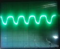
So i made some onother measurements with scope and i figured out that when i put bigger resistor in rc filter, for example 1ME (1ME and 100nF) thern i have small smaller dc signal but stable under discharge process. Problem is to sensing current via shund to atmega adc, resaults is unstable, picture belows shows signal on mosfet gates:
20160225_180107.jpg

Voltage is unstable from OP output (scope settings is 1V p-p), so that is because unstable current flow from battery.

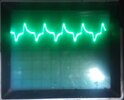
Onother interesting thing happening on circuit, when i put scope ground on battery ground there is signal like in picture from post before (charging and discharging capacitor), when i put scope gnd to gnd of OP, there is dc signal on current RC low pass filter also with smaller resistor - 100kE+100nF like before!!

the same thing happenig when put scope to Vcc pin of atmega MCU, signal is like in picture below, off course when i start discharge battery:
20160225_171944.jpg


audioguru2

Apr 6, 2004
12,026
Joined
Apr 6, 2004
Messages
12,026
Your ground wire is too thin so it acts like a resistor that has a votage drop across it. You need a "star" ground that has all grounds together at one point then there is no ground wire for a voltage to develop across.


denci

Apr 30, 2012
86
Joined
Apr 30, 2012
Messages
86
 TNX for your help audioguru I try with better ground and there is no such a signal as above any more!!

This was solution, I have very thin ground connection between battery ground and mcu ground so I add thicker wire.


denci

Apr 30, 2012
86
Joined
Apr 30, 2012
Messages
86
With spacing between battery wire (+ and - cable), signal is increasing it's shape like above, when wiring of battery so close together ther is just some little spikes appear on signal how can i avoid this problem, how can i get dc signal on discharging resistor while battery being discharged.


denci

Apr 30, 2012
86
Joined
Apr 30, 2012
Messages
86
is this parasite capacitance?

otherwise i solved problem with thicker positive and negative wire for battery connection but wires must be close together, if they aren't effect of capacitance appear again!


denci

Apr 30, 2012
86
Joined
Apr 30, 2012
Messages
86
I placed thicker wire in some ground places in order to avoid voltage drop as you said above and also put the thicker + and - connection wire for battery connection and problem solved when discharged current to above 2A is flowing, but when increasing current using PWM modulation as described above (increasing duty cycle) signal starts oscillating (picture from scope - some kind of charging capacitor).

So do i have improve ground further to decrease voltage drop??

All works fine but only because of oscillating i have wrong adc reading and i need to use adc averaging but also using this result not precise as i wanted to be!


denci

Apr 30, 2012
86
Joined
Apr 30, 2012
Messages
86
,

Your ground wire is too thin so it acts like a resistor that has a votage drop across it. You need a "star" ground that has all grounds together at one point then there is no ground wire for a voltage to develop across.
So i forgot to tell you that i have separate PCB board, one is power board and one is control board and only thin wires (flat cable) connecting them together so this is the main problem i must provide low resistance ground.

I have other question, why voltage on -op pin is not equal (aprox. 20% lower) then on +input pin (voltage follower orientation)??


audioguru2

Apr 6, 2004
12,026
Joined
Apr 6, 2004
Messages
12,026
You have not updated your schematic so maybe the LM324 opamp is still overloaded. Its output can source only 20mA so maybe the BD139 base current is higher.


denci

Apr 30, 2012
86
Joined
Apr 30, 2012
Messages
86
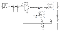
This is schematic you suggested me, only different is that there is no 22E resistors to mosfet gates.

battery_discharger.png.3f110c5bda94f0ac366995058a47b96c.png


audioguru2

Apr 6, 2004
12,026
Joined
Apr 6, 2004
Messages
12,026
The 22 ohm resistors are important. They prevent the Mosfets from oscillating at a high frequency.


denci

Apr 30, 2012
86
Joined
Apr 30, 2012
Messages
86
Ok i sould adding resistor.

So, do you still think that the signal spikes represented on picture above is reflected by poor ground, i must perform test once again i add some kind of "star" ground so all gnd is connected at one point with thicker wire.


denci

Apr 30, 2012
86
Joined
Apr 30, 2012
Messages
86
So i have changed filter and improve ground and provlem with currenr spikes is now solved.

I was testing circuit with power supply instead of battery and i figured out that current decreasing with bat voltage decreasing which is not allowed, maybe because too small mosfet drain to source voltage, i must find 22e resistor and put it into circuit also but most probably this is not because of gate resistor missing??

Voltage on - pin is little bot lowe again that voltage of +pin of op i must solve this too.


audioguru2

Apr 6, 2004
12,026
Joined
Apr 6, 2004
Messages
12,026
If the input voltage does not change but the battery current reduces then the voltage across R4 also reduces and the LM324 opamp inverts and amplifies (minimum DC voltage gain is 25000 times) this voltage drop so that the current change is reduced to almost nothing.

Check to make certain that the LM324 opamp output is not saturated as high as it can go (1.5V less than the power supply voltage) and that the gate voltages of the Mosfets are much higher than their source voltages (your schematic does not show a part number for the Mosfets) because most Mosfets need up to 10V.


denci

Apr 30, 2012
86
Joined
Apr 30, 2012
Messages
86
I am using mosfets IRFP460, regarding datasheet these transistor are suitable for project, i will check LM324 output voltage and then report values.

However problem is that battery voltage is reduce by high current so theoretically when 10A is flows out of battery, 5V is on R4, battery voltage could reach critical value arround only 9V (depends of battery healthy) and then source voltage of mosfet is only 4V, so mosfet can provide high current only on that condition, or not??


denci

Apr 30, 2012
86
Joined
Apr 30, 2012
Messages
86
I measured 5.5v on op output when input voltage is 1v, then voltage on r4 resistor is 0.75v, current is 1.6a, power supply voltage was set on arround 11.8v.

So if increasing voltage of power supply (which represent battery) than current is increas to arround 1a and than stops increasing which is logically, so mosfet most probably not suitable for such a battery voltage.


audioguru2

Apr 6, 2004
12,026
Joined
Apr 6, 2004
Messages
12,026
What is the part number of your Mosfets? It should be on your schematic.

If the (+) input of the opamp is 0.8V and the current in the 0.5 ohm resistor is 1.6A then the (-) input of the opamp is also 0.8V. When you increase the battery voltage and the current tries to increase then it increases the voltage at the (-) input of the opamp that causes its output voltage to drop and turn down the current so that the current does not increase.

Use an input of 0.8V and a fairly low battery voltage. Measure and post here the (+) input voltage, the (-) input voltage and the opamp output voltage. Then increase the battery voltage and measure and post them again.  


denci

Apr 30, 2012
86
Joined
Apr 30, 2012
Messages
86
Thanks but i gave an example of measurements in previous posts, mosfets are IRFP460, so only problem is that voltage on - pin does not follows voltage on + pin, regarding mosfet transistor Vds should not be a problem for this case.

I wondering why voltage on - pin is lower than voltage on + pin and ouput voltage of OP is lower as i exepected - in upper case only 5.5V.


audioguru2

Apr 6, 2004
12,026
Joined
Apr 6, 2004
Messages
12,026
If the voltage on the (-) input of the opamp is lower than the voltage on the (+) input pin then the output will go positive which turns on the Mosfet more which should increase the voltage at the (-) input AND CANCEL THE INCREASE AT THE OUTPUT.

The datasheet for the Mosfet (not ebay fakes?) shows a graph for a "typical one" with Vgs= 5.5V then current= 22A but some are more sensitive and some are less sensitive.


denci

Apr 30, 2012
86
Joined
Apr 30, 2012
Messages
86
I finally figured out where has problem been all the time, ground noise because battery connector.

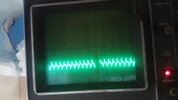
PWM signal is on picture below and you can see oscilating on ground.

I solved this by putting 0.47uF capacitor between battery connector and signal is smooth and now voltage on -pin is the same as on +pin (which is suprising me, so voltage inequality reflected by input noise of OP????) but i must perform test also with higher current but for now this is part of solution.

20160421_133950.jpg


denci

Apr 30, 2012
86
Joined
Apr 30, 2012
Messages
86
If i burdened battery or. increase discharge current reading of voltage becomes smaller.

I have 33kE and 11kE resistors serial from battery + pin to ground, so this is resistor divider, so if no current flows from battery there is normal reading, when current is higher reading is wrong or smaller as i said, for example battery voltage is 11.5V, adc reading is only 9.5V.

 
Top