Current monitor/sensor

denci

Apr 30, 2012
86
Joined
Apr 30, 2012
Messages
86
schemeit-project_(3).thumb.png.39f667e231429d2541b53460fabca305.png


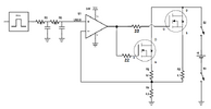
So, this is circuit i want to make controled battery discharge with and as i said don't work as i expected.

When i connect power supply unlimitet current want to flow through circuit bit i don't know why?

 Maybe you are confused with my comment about power supply, no, i just use power supply from this forum to power this discharged circuit!

 

denci

Apr 30, 2012
86
Joined
Apr 30, 2012
Messages
86
Transistor is burned out again so i just wondering that the main problem is that at power supply present and before output of MCU provide zero voltage to + input of OP very high current through BD139 and in bases of output transistor because battery not connected at start.

As is said i have no problem with circuit where i use PNP uput transistors because at start no current was flow through circuit because no base current flow when battery was not connected to PNP emmiters.

But i eliminated that version of circuit because problem of voltage gain and oscillations like you said but i must introduced some solution in this circuit to avoid high current flow when battery is not  connected onto collectors.


audioguru2

Apr 6, 2004
12,026
Joined
Apr 6, 2004
Messages
12,026
When the battery voltage is low or when the battery is not connected to the collectors of the output transistors then when the BD139 turns on its load is the base-emitter diodes of the output transistor in series with the very low value resistors causing a very high current in the BD139. I said yesterday to add a resistor between the emitter of the BD139 and the bases of the output resistors to limit the current. 


denci

Apr 30, 2012
86
Joined
Apr 30, 2012
Messages
86
Thanks!

I tried this and works fine, i put the 680E resistor between emmiter and bases, but there is one think, it can't possible to make no current flow throught circuit if battery disconnected, some current always flow into transistors, around 1.5ma regarding my simulation.


denci

Apr 30, 2012
86
Joined
Apr 30, 2012
Messages
86
Have you any idea how to avoid this effect?

It could be ideal that no current flow through output transistor when battery is not connected onto circuit and 0V is on discharge power resistor via OP feedback.


audioguru2

Apr 6, 2004
12,026
Joined
Apr 6, 2004
Messages
12,026
If there is a positive input voltage to the opamp (+) input, the current flows from the emitter of the BD139 through the base-emitter diodes of the output transistors and through the low value resistors to ground. The 1k emitter to ground resistor of the BD139 also has current in it. When there is 0V on the discharge power resistor then there will be no current in it and no current in any other part.


denci

Apr 30, 2012
86
Joined
Apr 30, 2012
Messages
86
Yes, thats thrue, but when i put resistor between BD139 emmiter and two output transistor bases this mean that if no zero voltage on power resistor (beacause of some unfourable reasons) current flows through output transitor in any case also without battery because there is forward biased.

I hope that i am right.


denci

Apr 30, 2012
86
Joined
Apr 30, 2012
Messages
86
If there is a positive input voltage to the opamp (+) input, the current flows from the emitter of the BD139 through the base-emitter diodes of the output transistors and through the low value resistors to ground. The 1k emitter to ground resistor of the BD139 also has current in it. When there is 0V on the discharge power resistor then there will be no current in it and no current in any other part.
When i have 0V on + input pin of opamp LM324 then i have 24V on ouput and bd139 is turn on end also when i put resistor 220W between BD139 emmiter and ouput transistor bases. This is all againts how i want to circuit works, maybe something wrong with opamp?

Is there any chance to no current flow at all throught circuit even battery is no conected and regardless what in input voltage on + input pin of OP, because anyway there is additional relays which turn on battery and it starts discharging?


audioguru2

Apr 6, 2004
12,026
Joined
Apr 6, 2004
Messages
12,026
When i have 0V on + input pin of opamp LM324 then i have 24V on ouput and bd139 is turn on end also when i put resistor 220W between BD139 emmiter and ouput transistor bases. This is all againts how i want to circuit works, maybe something wrong with opamp?

Is there any chance to no current flow at all throught circuit even battery is no conected and regardless what in input voltage on + input pin of OP, because anyway there is additional relays which turn on battery and it starts discharging?
No, the opamp and transistors are a follower. 0V input gives 0V output at the 0.5 ohm resistor. +1V input gives +1V output at the 0.5 ohm resistor. +10V input gives +10V output at the 0.5 ohm resistor producing a current of 20A.

220 ohms between the emitter of the BD139 and the bases of the output transistors limits the current in the BD139 and reduces the base current in the output transistors.

If the battery is not connected then if the input of the opamp has a positive voltage then the BD139 will more current than when the battery is connected.

I cannot remember why you want to kill a battery by discharging it. 


denci

Apr 30, 2012
86
Joined
Apr 30, 2012
Messages
86
No, the opamp and transistors are a follower. 0V input gives 0V output at the 0.5 ohm resistor. +1V input gives +1V output at the 0.5 ohm resistor. +10V input gives +10V output at the 0.5 ohm resistor producing a current of 20A.

220 ohms between the emitter of the BD139 and the bases of the output transistors limits the current in the BD139 and reduces the base current in the output transistors.

If the battery is not connected then if the input of the opamp has a positive voltage then the BD139 will more current than when the battery is connected.

I cannot remember why you want to kill a battery by discharging it. 
This is exactly the main problem in circuit, if battery not connected and positive voltage apply in + iput of OP by chance, so this mean that high current try to flow through BD139 and 220E resistor and buri it.

Circuit is for battery test purpose, programmable cotrol discharger to test battery healthy and compare quality between each battery pack.

So i have a big problems because PCB is already made and no big chance are allowable there any more, so i try to find solution to current flow in ouput transistor base.

Maybe other solution is available there because as i said there is relays too and when relays is not activated i wan to no current flow except we select program to start discharge the battery.

TNX for your helps!


denci

Apr 30, 2012
86
Joined
Apr 30, 2012
Messages
86
It's maybe batter to add 100E restor from 24V supply to BD139 collector and onother 100E resistor between emmiter and output transistor bases?

Or there should be additional relay to provide open circuit while battery is disconnected and no current flow when battery isnt present at all?


audioguru2

Apr 6, 2004
12,026
Joined
Apr 6, 2004
Messages
12,026
Of course the transistors will not work when you need them to work if you use resistors to limit their current. Also the current will still be fairly high and the added resistors will get hot.

Why not use Mosfets instead? They use NO base current. When the battery is dead or is missing then the circuit will use only the 1mA to 2mA of supply current for the opamp.

battery discharger.png


denci

Apr 30, 2012
86
Joined
Apr 30, 2012
Messages
86
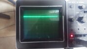
Hello again, i have had problem with RC filter from PWM but i solve it with proper resistor and capacitor value and i get DC signal into positive pin of OP, see picture below.

20160224_171559.jpg

When i put 100 bit value i get around 0,5V which is OK.

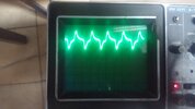
There is one onother problem which i have still not solve till now, when i connect battery and start to discharge it the signal from RC is like below:

20160224_171643.jpg

Do you know why this happening??


denci

Apr 30, 2012
86
Joined
Apr 30, 2012
Messages
86
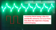
i testing also direct on pwm pin od MCU and when battery is charging there is a lot of noise in ground, in upper case is 10% duty cycle so i don't know if that kind of signal is reflected by RC loos, or??

Maybe OP is critical here in this circuit??


audioguru2

Apr 6, 2004
12,026
Joined
Apr 6, 2004
Messages
12,026
Why are you using poorly filtered PWM instead of variable DC?

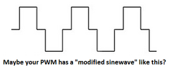
I don't see any "noise" on the 'scope. Instead I see the filter capacitors charging and discharging. Maybe the signal is a modified sinewave? 

modified sinewave PWM.png

 
Last edited by a moderator:

denci

Apr 30, 2012
86
Joined
Apr 30, 2012
Messages
86
Yes, but why this happening when I try to discharge battery through 0.5E resistor, current is controlled with software regulated PWM output, is this signal appear because OP oscillate via feedback??

I just wondering how to always provide DC signal to load resistor to ensure that always flow also dc current through system.


audioguru2

Apr 6, 2004
12,026
Joined
Apr 6, 2004
Messages
12,026
I think the very high discharge current in the ground wire is modulating the 0V of the PWM circuit or the opamp circuit. Use a thicker ground wire.

 
Top