help with IR2110 chips

Alec_t

Jul 7, 2015
3,817
Joined
Jul 7, 2015
Messages
3,817
I think what your 'guy' is saying is that if the Vdd supply is 5V then driving the Hin and Lin pins with 3.3V logic is marginal. The IR2110 datasheet says the chip is 3.3V logic compatible, so in that case Vdd should also be 3.3V, not 5V.
 

Maglatron

Jul 12, 2023
2,025
Joined
Jul 12, 2023
Messages
2,025
THANK YOU jees that guy couldn't give me a strait answer, because in the sim it doesn't work if the, VDD is 5v and the signal is 3.3v. only VDD 5v and signal 5v or VDD 3.3 and signal 3.3 would this work having the LM7805 to drive the VDD and the Arduino and have the Arduino give out 5v for the signal pins?? thanks 1727509031970.png
 
Last edited:

Maglatron

Jul 12, 2023
2,025
Joined
Jul 12, 2023
Messages
2,025
is it a good idea to put in decoupling 100nf caps over the vcc and ground BTW?
 

Alec_t

Jul 7, 2015
3,817
Joined
Jul 7, 2015
Messages
3,817
I'd use 5V from the Arduino and 5V for the logic, also read the IC datasheets for the manufacturer's recommendations on decoupling caps. Each IC would generally benefit from a decoupling cap as close to its supply pins as is practicable.
 

Maglatron

Jul 12, 2023
2,025
Joined
Jul 12, 2023
Messages
2,025
like in the image in post 762 for the VDD the power for the Arduino and the signal logic? just to clarify and make sure! thanks
 
Last edited:

Alec_t

Jul 7, 2015
3,817
Joined
Jul 7, 2015
Messages
3,817
I'm not familiar with the Arduino's power requirements, but if it accepts 5V then the 7805 should do the job for it and the IR2110s.
 

Maglatron

Jul 12, 2023
2,025
Joined
Jul 12, 2023
Messages
2,025
I'm not familiar with the Arduino's power requirements, but if it accepts 5V then the 7805 should do the job for it and the IR2110s.
ok cool because the Arduino both accepts and broadcast 5volt on the signal pins!! if broadcasting is the correct terminology :)
 
Last edited:

bertus

Moderator
Nov 8, 2019
3,837
Joined
Nov 8, 2019
Messages
3,837
Hello,

Have a look at the figures 2 and 3 in the posted datasheet.
There you see the decoupling capacitors.
There is one of 10uF and one of 100nF.

Bertus
 

Maglatron

Jul 12, 2023
2,025
Joined
Jul 12, 2023
Messages
2,025
I don't get it can I get some help! where do I put my decoupling caps? in mine pins 3 and 9 are not connected I think mine is most similar to the first one! do I just put them between pin 3 to GND. On pin 9 of mine it's only 5volt!! what should I do!!??
1727605679157.png1727605696578.png1727607234271.png1727607760224.png
no decoupling caps shown on this schematic! actually I think I see them c4 c3 c7 c8
 
Last edited:

bertus

Moderator
Nov 8, 2019
3,837
Joined
Nov 8, 2019
Messages
3,837
Hello,

Yes, the decoupling capacitors are between Vdd and Vss (ground).

Bertus
 

Maglatron

Jul 12, 2023
2,025
Joined
Jul 12, 2023
Messages
2,025
thanking you!! PROGRESS MUHAHAHAHAHAAAAA

so I.ve made a start on the new inverter! have pics when done

nearly finished the inverter! photos soon

almost finished!

Moderators note: compacting thread
 
Last edited by a moderator:

Maglatron

Jul 12, 2023
2,025
Joined
Jul 12, 2023
Messages
2,025
Finished!!!
 

Attachments

  • DSCF0398.JPG
    DSCF0398.JPG
    447.5 KB · Views: 3
  • DSCF0399.JPG
    DSCF0399.JPG
    389.6 KB · Views: 3
  • DSCF0400.JPG
    DSCF0400.JPG
    513.5 KB · Views: 3
  • DSCF0401.JPG
    DSCF0401.JPG
    283 KB · Views: 3
  • DSCF0402.JPG
    DSCF0402.JPG
    382.6 KB · Views: 3

Alec_t

Jul 7, 2015
3,817
Joined
Jul 7, 2015
Messages
3,817
Hopefully all those long wires won't cause problems if they're handling high frequency voltages/currents.
Have you left space for heatsinks on the MOSFETS if they're needed?
 

Maglatron

Jul 12, 2023
2,025
Joined
Jul 12, 2023
Messages
2,025
there is space for sinks (slim sinks)!, can't see it being a problem! But I take what you say onboard, and will try to make the cables as short as possible. But BTW I did over compensate with the long wires because you can always trim back wire than putting it back on! Is 50Hz considered "high" frequency? and also I put in a USB slot so that I can connect strait to the Arduino no probs, this part of the project is looking rather good to be fair; the wires that cross the entire board, blue and green are for the signal pins, an questions fire away!!! :D
 
Last edited:

Maglatron

Jul 12, 2023
2,025
Joined
Jul 12, 2023
Messages
2,025
so the "guy" on the other forum says
was a waste of time....
but if you have read this couple of lines ... you also could imagine that your effort for the past days ... was the same.
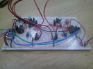
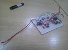
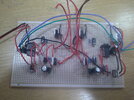
I´ve claerly written that a breadboard will not work. The used strip board is nothing better than a breadboard.
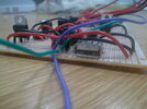
GND plane is mandatory .. also - as written - short, low inductance wiring.
I miss all this.

Again: designing switching power applications is no simple task. Nothing fro a beginner at all.
The way you did .. simply does not work.
Not in the meaning that it does not function at all ... but I highly doubt it works reliably and it works according EMI/EMC regulations, and it works for several weeks.
I assume sooner or later it will kill itself.

I don´t want to discourage you doing electronics - but maybe you should do some simpler tasks first. I guess I did several years of rather advanced electronics design before I did a switch mode regulator. And for sure I still made mistakes.

I´m sure this is not what you wanted to hear. You invested so much time...
But what should I say? I was raised to say the truth. And I´m not good in sugarcoating bad news. Sorry for this.

what are your thoughts Mr Alec_t?? appreciated
I think he's just acting superior knob
 
Last edited:
Top