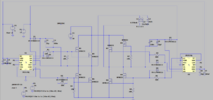
I thought the circuit runs off 12v and the input to node 3 is the output of the rectified AC voltage from the coils!! are you sure that is correct, Im almost certain that the 12v should be there and the voltage to the INPUT to the MOSFETS is a different voltage; which is from the rectified voltage from the power coils do you get what I mean the 12v into the chip should be separate from the input to the FETs and until I manage to spin it up we can't tell how much voltage it makes
so I have purchased PCB wizard and not I want to know if any body can tell me how to add holes in the PCB to be bigger to accommodate for the thicker legs on the ultra fast diodes?
downloaded trial in the meantime just finished and after, I realized that you cant save!! just seen the I didn't put in the ground for two of the MOSFETs
yep seen it I purchased the program get it sent through email takes 1 to 2 working days! I'm going to go with "nextpcb" website £5 per board minimum order 5 so £25 for the boards and the program £30 round off to £60 with post much better than that guy on the other forum trying to charge me £300 for 1!! when I get 5 this way and I'm sure they will come in at some point
it says 100% 0f connections made but as you can see in the blaxk circles there are little jumps over the tracks which I guess are wires any body know what's up!!
still crap I found KiCAD sure that it has been recommended before, but I forgotten about it, it does two sided boards so I think I wasted my money on the PCB wizard! we will see how KiCAD compares!
")

 do you get what I mean the 12v into the chip should be separate from the input to the FETs and until I manage to spin it up we can't tell how much voltage it makes