I think the whole circuit is crap there's no fluctuatio on the signal lines and I don't know why there isn't any fluctuation on the input to the primary of the transformer
start from scratch?
as far as I can tell it should be correct to be fair I don't know why it doesn't work, could it be when I imported the .subnet files into the program perhaps? I cant even get a wave from the pulse generators!! now that is odd
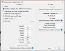
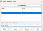
It's a Spice .param directive (command), entered as such directly on the schematic, using the .op tool at the end of the toolbar.
The curly brackets tell LTS to calculate the contents, using values and parameters which have already been defined.
Your post #86 defines the pulse parameters correctly, apart from limiting the simulation to 100m (i.e only a fraction of a pulse cycle) and without any dead-time. LTS will adjust the timing to allow for the finite rise and fall times.
For future reference, I suggest getting into the habit of using the 'Label Net' tool to give a more meaningful name to a node than 'N001'.
In your posted .asc file the two pulse generators should have ground attached at the bottom.
The param editing (post #94) is correct.
21V for V1 is too high. That will kill the gates on some MOSFETs. Never run components at their Absolute Maximum ratings if you want them to have a long and happy life.
meant 12v
don't know how i missed the ground, stupid of me really. I don't know where you are on about the "N001" thing, Okay trying to run it now wish me luck!
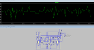
Okay thats more like it now I have proper readings, so the part I wish to know now, is how to speed up the simulation, because right now its going like 20ms per second (very slow) but your top bloke for helping me out very nice of you im now generating a square wave on pulse generator 5 but no fluctuation on pulse gen 4 i have ring on the inductor thats in place of the motor which is good reacting properly but its at very slow sampling rate how to increase sample rate and i just clocked on to what you were saying about N001 thats the name of the signals on the graph ok getting there. going to eat food il be back on in about 45 mins but take your time mate no rush!
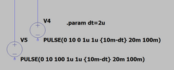
v5 no pulse coming out?
sussed it! needed to put delay 10m, and i forgot the m
not sure what I'm looking at and how to change the label net option but things are happening so I'm happy at the moment!
how do I change the rate that thee simulation runs?
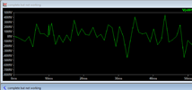
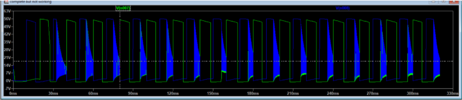
is this looking correct to you? why is the ringing is the dead time working correctly?