Full Wave Rectifier and Bridge Rectifier
Full-Wave Rectifier The rectifier is an electrical circuit that converts alternating current into direct current. As discussed in the previous article, the half-wave rectifier converts only the half-cycles of the alternating current either positive or negative depending upon the orientation of the diode.
Full-Wave Rectifier
The rectifier is an electrical circuit that converts alternating current into direct current. As discussed in the previous article, the half-wave rectifier converts only the half-cycles of the alternating current either positive or negative depending upon the orientation of the diode. It was also discussed that the efficiency of the half-wave rectifier is less as it utilizes only half-cycles and other halves are blocked/ not present to the output. Moreover, the capacitor filter was used to eliminate ripples and to smooth the output signal. In a half-wave rectifier, the ripple frequency equals the input frequency. These half-wave rectifiers are used in low-power and low-cost power supply circuits.
The efficiency of the rectifier can be improved by utilizing both cycles of input alternating current. The circuit which utilizes both half-cycles to convert alternating current to direct current is termed a full-wave rectifier. The full-wave rectifiers are more efficient compared to half-wave rectifiers and use more than one diode in the circuit.
Full-Wave Rectifier Circuit using center-tapped Transformer
The transformer having split secondary winding with the center-tap connected to the resistive load through two diodes. The transformer usually produces current with a 180-degree phase difference in the secondary winding depending on the dot location on the windings.
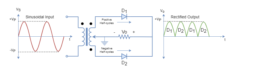
In the above figure-1, the full-wave rectifier using a center-tap transformer is shown. A sinusoidal wave applied to the primary of the center tap transformer is transformed into the secondary winding and voltage potential is developed on the secondary side. The potential developed in the secondary alternates every half cycle. The output of the full-wave rectifier has a time period half of the input or has a frequency double to that of the input signal.
The rectification process is explained for each half-cycle.
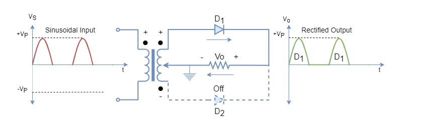
During the first half-cycle, the potential developed forward biases D1 diode and reverse biases diode D2. The positive half-cycle passes through the D1 diode and develops the voltage across the load resistor as shown in figure-2. The current direction through the load resistor and the voltage polarity across it, are to be observed and should remain the same during the negative half-cycle.
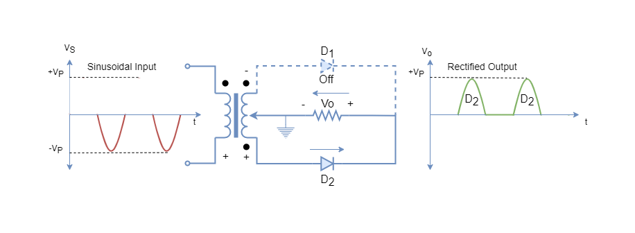
During the second half-cycle, the voltage polarity across secondary winding is shown in figure-3 which is due to reversal of polarity across the primary winding. Under this polarity, the D2 diode is forward biased and the D1 diode is reverse biased. Hence, the D2 diode allows the current to flow through the load resistor whilst the D1 diode remains off during this half-cycle. The current direction through load resistor and voltage polarity across it remains the same as observed during the first half-cycle. This arrangement of diodes with a center-tap transformer leads to a uni-directional current flow through the diode. The rectification of alternating current takes place during both half-cycles i.e. for the whole time period of a sinusoidal signal.
The rectification process continues, similarly, by alternating the current flow through diodes D1 and D2 for the approaching cycles.
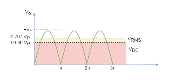
The average of the full-rectified sinusoidal wave is given by:
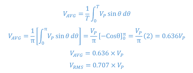
The average output of the half-wave rectifier, as seen in the previous article, is 0.318 times the peak voltage. But in full-wave rectification, the average output has doubled and due to which the average power delivered has also quadrupled. Hence, leading to a more efficient rectification process as compared to half-wave rectification.
Diode Bridge Rectifier
The transformers having a center-tap secondary winding are more costly and larger in size due to the presence of two windings on the secondary side. Because of this, in power supplies, mostly signal winding transformers are used and a special diode bridging is used to perform full-wave rectification. The diode bridge can be made using four similar diodes or a complete off-the-shelf diode bridge package can be obtained to perform full-wave rectification. The diode bridges are available in different ratings and specifications to fit into different applications and circuit designs.
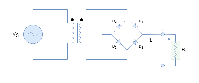
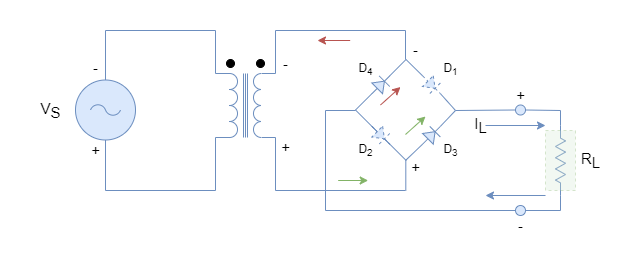
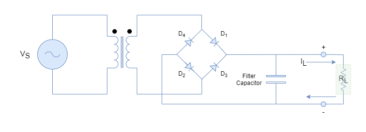
A simple diode bridge full-wave rectifier is shown in figure-5 and four power diodes are used here instead of two diodes in the center-tap transformer. During the first half-cycle, the voltage polarity across the diode bridge is shown in figure-6 which makes the diodes D1 and D2 forward biased. The other half of the bridge i.e. diodes D3 and D4 remain in off condition. This biasing arrangement of the bridge causes the flow of current through the load and a voltage appears across it. The direction of current and voltage polarity across the load is depicted in figure-6.

Similarly, for the next cycle, the polarity reverses due to alternating sinusoidal source and voltage across Diode Bridge is shown in figure-7. The voltage polarity makes diodes D3 and D4 forward bias this time whilst diodes D1 and D2 remain off. The direction of current through the load and voltage polarity across it, remains unchanged which means even after reversal of polarity of input sinusoidal wave the polarity across the load remains unchanged.
The diode bridge circuit performs full-rectification of successive alternating cycles. The drawback of the bridge rectifier compared to the center-tap transformer is that it uses two diodes at a time for rectification which causes double forward voltage drops.
Full-Wave Rectification Example
The power supply circuit of the previous article using a half-wave rectifier is used here to compare the results. The voltage source of 220VRMS with 100:1 transformer was used to supply a load of 1 kΩ Using bridge full-wave rectifier:
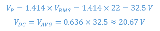
An approximate 20 VDC appears across (forward diode voltage drops are ignored to keep things simple) the load and the current flow through 1 kΩ load is:
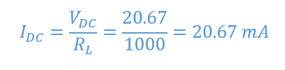
The power delivered to the load using a full-wave bridge rectifier:

The full-wave rectifier delivers twice the voltage and quadruple power to the load as compared to the half-wave rectifier. It makes the full-wave rectifier more efficient and for the same voltage power supply a smaller transformer can be utilized compared to using a half-wave rectifier. For example, using a half-wave rectifier, a 10:1 ratio transformer is used to supply approx. 10 VDC to the load when input is 220VRMS. However, a 5:1 ratio transformer can be utilized to deliver the same load voltage using a full-wave bridge rectifier.
Ripples and Filtering Capacitor
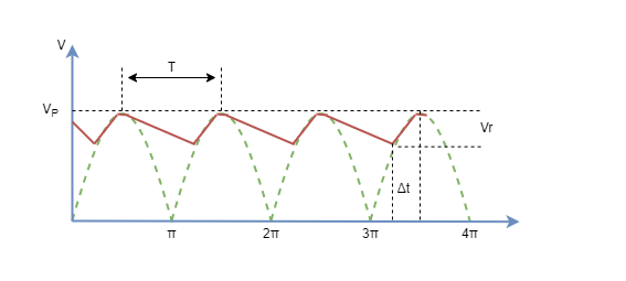
However, an increase in efficiency comes at the cost of ripples which are doubled compared to the half-wave rectifiers. The increase in ripples is due to an increase in frequency which has doubled. The ripples are undesirable elements of any electronic circuit and the output of power supplies can be smoothed using a filtering capacitor. The peak rectifier circuit with capacitor filter is shown in figure-8.
The capacitor acts as storage or reservoir and supplies the load during the OFF period. The value of the capacitor should be large enough so that its time constant (RC) >> time period of the sinusoidal signal. The capacitor charges when the voltage is increasing up to the peak voltage and then it starts discharging by supplying current to the load. The capacitor keeps supplying the load until the next cycle when the voltage starts increasing again. For each cycle capacitor charges and discharges when voltage is increasing and decreasing, respectively. The during the conduction period (Δt), diodes supply the load and charges the capacitor.
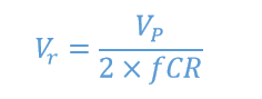
The ripple voltage for a full-wave rectifier is given by the following formula and note that ripple frequency has doubled as compared to half-wave rectifier:
For example, if the desired ripple voltage is 1V for the above example then the value of the capacitor filter is:
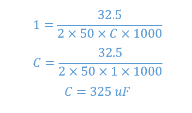
So, a capacitor of 325uF is required to have a ripple voltage of 1 V for a bridge rectifier power supply given in the above example.
The diode conduction period can be approximated by the following formula:
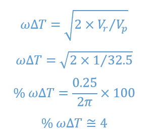
The diodes will conduct during only 4% of the total period and the rest of the period load will be supplied by the capacitor.
The full-wave rectifiers using bridge diodes are mostly used in power supplies and rectifiers. The drawbacks are the use of two diodes and an increase in ripples. Both of these factors could lead to distortions and harmonics in circuits.
Conclusion
- The full-wave rectifiers are most commonly used in the rectification process because they are more efficient compared to half-wave rectifiers.
- The full-wave rectifiers can be constructed by using a center-tap transformer or bridge diodes. The center-tap rectifier used a single diode for conduction whereas the bridge-diode two diodes for conduction.
- The center-tap full-wave rectifier uses a two-winding transformer increasing the size and cost. Whilst, bridge-diode rectifier uses two diodes for rectification at a time i.e. double forward voltage drop and addition of non-linear device.
- The average voltage or DC voltage delivered by a full-wave rectifier is 0.636 times the peak voltage which is twice the voltage delivered by the half-wave rectifier. Ultimately, the power delivered becomes quadrupled.
- The ripple factor is double in the full-wave rectifier because of the double frequency.
- The ripples can be reduced using a capacitor filter and the time constant of the filter capacitor should be large enough so that it should not completely discharge during the supply period.


