Power Diodes and Rectifiers
Power Diodes and Rectifiers The diode is a semiconductor device that allows current to flow in only one direction when it is forward biased and blocks the current in reverse bias condition. This has been explained in the previous article of “The Signal Diode”.
Power Diodes and Rectifiers
The diode is a semiconductor device that allows current to flow in only one direction when it is forward biased and blocks the current in reverse bias condition. This has been explained in the previous article of “The Signal Diode”. This feature of the diode resembles a switch or valve and can be utilized to allow passage of current at certain desired conditions only.
In the “The Signal Diode” article, the most popular applications of diodes have been explained and one of them is Rectification. The Rectification means, in electrical terms, conversion of alternating current (AC) to direct current (DC) using electronic equipment. The alternating current is bidirectional, having positive and negative values, and the direct current is unidirectional, either positive or negative. The direct current signal should ideally provide a continuous and constant value. The rectifier circuits are mostly used in power supplies, inverters, and battery chargers, etc. The diodes used in high-power circuits are termed Power Diodes.
Power Diode
The power diode has the capability to pass high current through it and can withstand high voltage. It has a larger PN-junction compared to the simple diode and as such can allow several hundred amperes to flow through it. However, the larger PN-junction of the power diode, makes it less responsive to high-frequency signals. Commercially available power diodes are used in battery chargers, inverters, and rectifiers, etc. Due to their high voltage withstand capability they are used as freewheeling diodes to protect against voltage spikes/ surges.
The power diodes have a greater breakdown voltage and are generally classified into:
- General Purpose
- Fast Recovery
- Schottky
The general purpose power diodes are the most commonly used in electronic circuits involving power supplies and rectifiers. The Glass Passivated type 1N400X (1N4001 to 1N4007) series of power diodes have voltage rating from 50 V to nearly 1000 V with a forward current bearing capacity of 1A at these voltages.
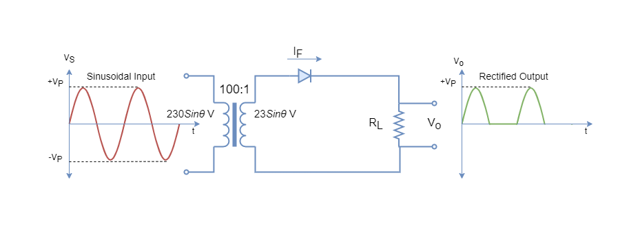
A simple power diode rectifier circuit is shown in the following figure. This is the simplest example of the rectifier and termed a half-wave rectifier which is explained below in the article.
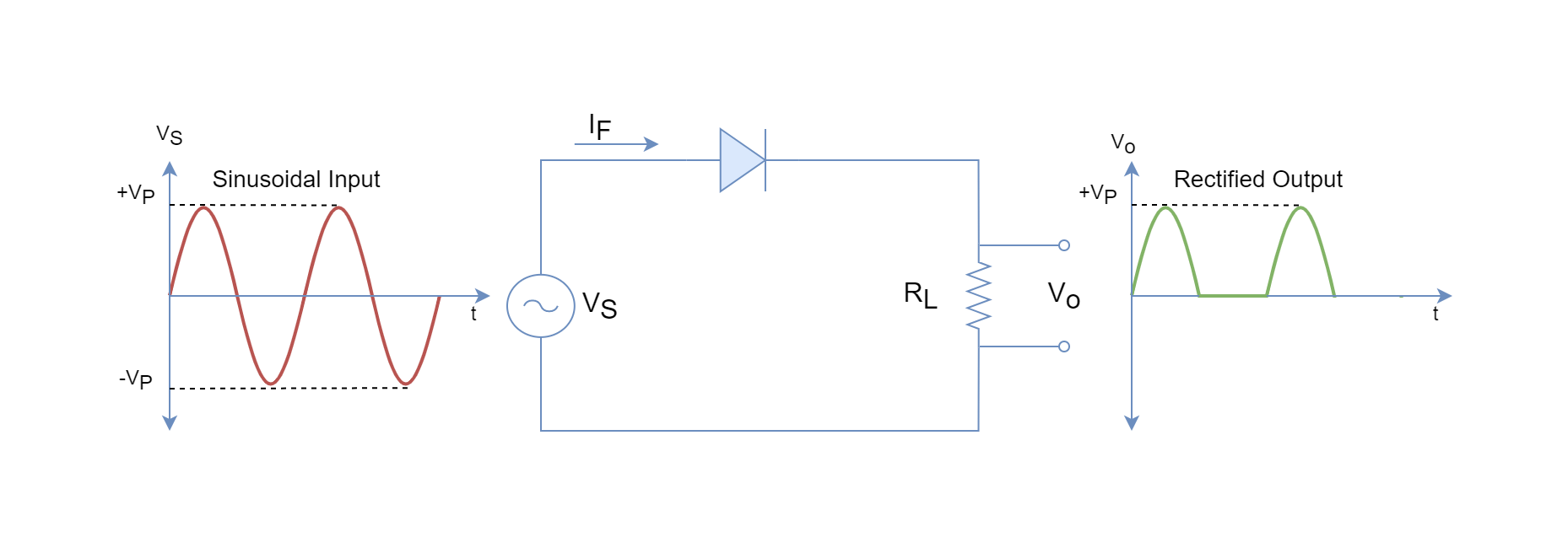
The half-wave rectifier has a sinusoidal input and the power diode conducts (ON) only during the positive (+) cycle (half of the full-cycle) when the anode is more positive with respect to the cathode. In the next half-cycle (negative one), the power diode blocks (OFF) the current until the next positive half-cycle. The voltage appears across the load resistance during the ON period only. The input sinusoidal wave has been clipped off during the negative half-cycles and only positive half-cycles appear across the output. The rectification during only half-cycles terms the circuit as a half-wave rectifier.
In addition to positive cycle rectification, the diodes can be used to rectify during full-cycle and are called “Full-Wave” or “Bridge” rectifiers.
Rectifiers
The rectifiers based solely on diodes are uncontrolled rectifiers in which the output cannot be controlled and remains constant. The rectifiers based on Silicon-Controlled Rectifiers (SCR) are controllable rectifiers and the output of rectifiers can be controlled through firing angles of SCRs.
Half-Wave Power Rectifier Circuit
Continuing with the above half-wave power rectifier circuit, a half-wave rectifier circuit for conversion of mains supply (230 VACRMS) to 10 VDC is explained for understanding. Before, the basic calculations are revised to cope up with the upcoming explanation of the half-wave rectifier circuit.
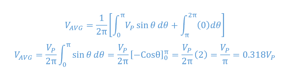
The average value of the periodic signal is given below:
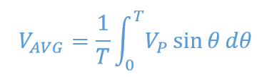
For a sinusoidal signal, the positive half-cycles equals negative half-cycles, and such cancels out to zero average. For a half-wave rectifier, the average is given as follow:
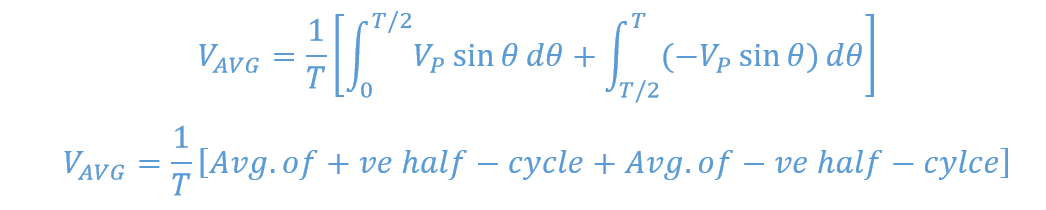
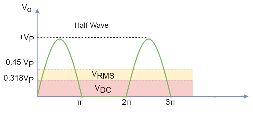
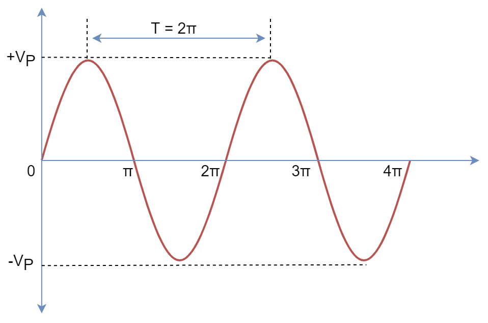
Figure 3: Half-Rectified Sinusoidal wave.
The half-rectified figure shows, Time Period = 2π and no (zero) signal during the negative (-) half-cycle, resulting in:
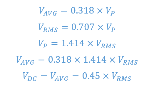
Similarly, the root means square (RMS) represents the DC equivalent of an AC signal for power calculations and calculated as:

In a nutshell, for a half-wave rectifier:
Now, consider the following half-wave rectifier circuit in which a transformer (100:1) is used to step down the mains supply from 230VAC to 23VAC.
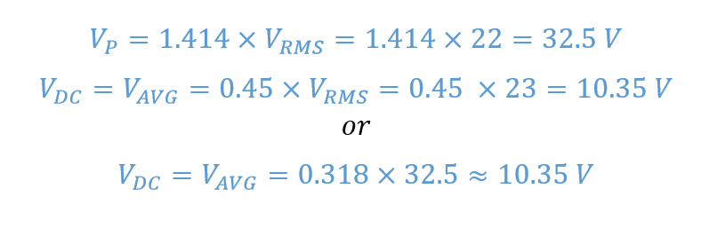
Using the above formulas on the secondary side of this circuit:
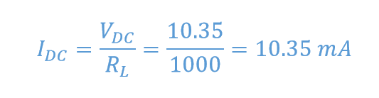
So, a 10VDC appears across the 1 kΩ load. The average current flowing through the load:
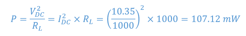
For power dissipation, the following formula can be used on the supposition that it is purely a DC signal.
In half-wave rectifiers, only 50% of the input signal is converted into a DC signal, and the rest of the 50% is wasted due to the OFF state of the rectifier. Due to this, the less average value is delivered to the load and the circuit is not that efficient. Further to this, the half-wave rectifier is prone to ripples due to a larger stop period and frequent switching. The ripples cause fluctuations and are undesired in electronic and digital circuits. The ripples cause unnecessary heating, distortion, and noise etc. Especially, in digital circuits, it may cause malfunctioning and give undesired output.
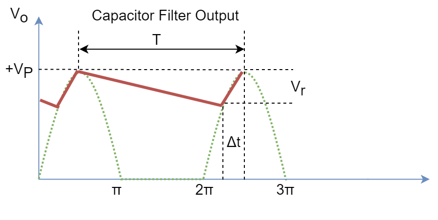
The ripples can be primarily avoided using a shunt capacitor and called filter capacitor or smoothing capacitor because of its purpose in the circuit. A half-wave rectifier circuit with a capacitor filter is shown in the following figure. The circuit is called a peak rectifier.
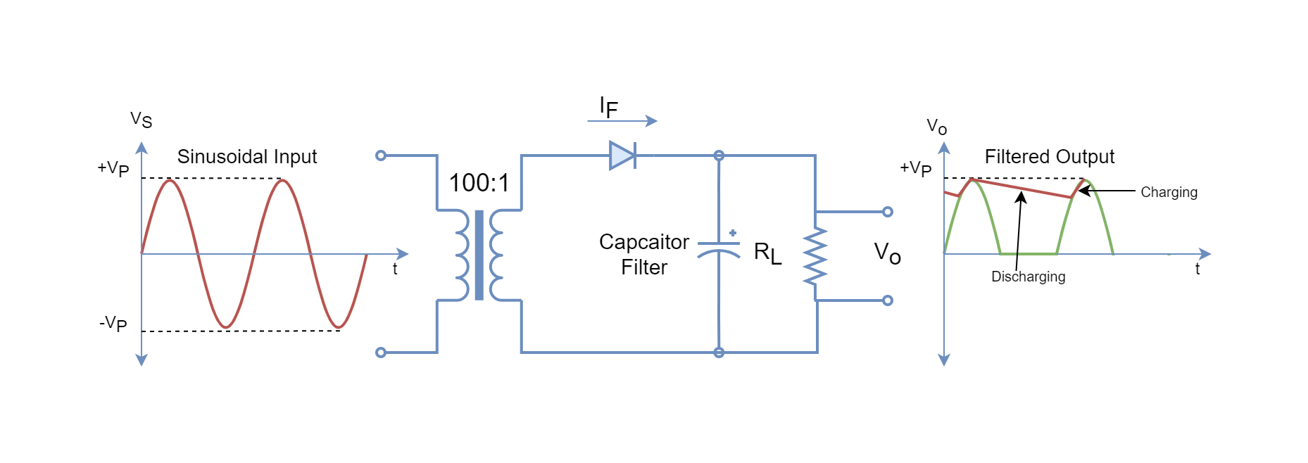
The capacitor acts as a storage or reservoir and supplies the load during the OFF period. The value of the capacitor should be large enough so that its time constant (RC) >> time period of the sinusoidal signal. The capacitor gets charged to peak voltage on the initial positive cycle and when the negative cycle starts, the diode cuts off supply to the capacitor. The diode supplies the load and charges the capacitor during the (Δt) period. For the rest of the period, the capacitor supplies the load current until input voltage becomes equal to capacitor decaying voltage during the next positive cycle. The capacitor recharge starts and the process keeps repeating.
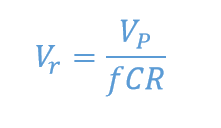
The ripple voltage for a half-wave rectifier is given by the following formula:
The half-wave rectifiers are seldom used because of their low average output and half of the input cycle is not utilized. They can be found in low-power or cheap power supplies. Instead, the full-wave or bridge rectifier is used because of its high average output and utilizes both input cycles.
Conclusion
- The power diode is used for applications involving high current and high voltage.
- Power diodes have a larger PN-junction and, thus, have greater breakdown voltage.
- Power diodes are less responsive to high-frequency signals such as greater than 1 MHz signals.
- Power diodes are used in power supplies, battery chargers, rectifiers, and inverters, etc.
- The rectifier converts alternating current into direct current.
- The half-wave rectifier uses a single power diode to convert the half-cycle of the input cycle.
- The average or DC output of the half-wave rectifier is VDC = 0.318XVP or 0.45XVRMS.
- The half-wave rectifier DC output is low compared to the input, half-cycle of input goes unutilized and is prone to ripples.
- The ripples can be reduced by the use of a capacitor filter across the load and called a peak rectifier.
- The capacitor should be large enough to have a greater time constant (RC) than the time period of the input signal.


