The Signal Diode
The signal diode is a semiconductor device that is based on the PN junction theory, previously described in the article. It is the simplest, non-linear semiconductor device and is found in almost every electronic circuit.
The signal diode is a semiconductor device that is based on the PN junction theory, previously described in the article. It is the simplest, non-linear semiconductor device and is found in almost every electronic circuit. As we learned from the previous article, two currents can flow in the PN junction namely diffusion and drift current. The diffusion current is due to majority carriers when the voltage barrier of the depletion layer is overcome. Whilst, the drift current is due to minority carriers and depends on the operating temperature. The signal diode exhibits the flow of both currents and, keeping this in mind, it is good to describe the ideal diode first.
Ideal Diode
The ideal diode is the one that does not have any drift current due to minority carriers and no barrier to overcome. It is simply, an ON & OFF device depending on the polarity of the supply voltage. The symbol of the diode and its V-I characteristics (ideal) along with states of the diodes are shown in the following figure (1).
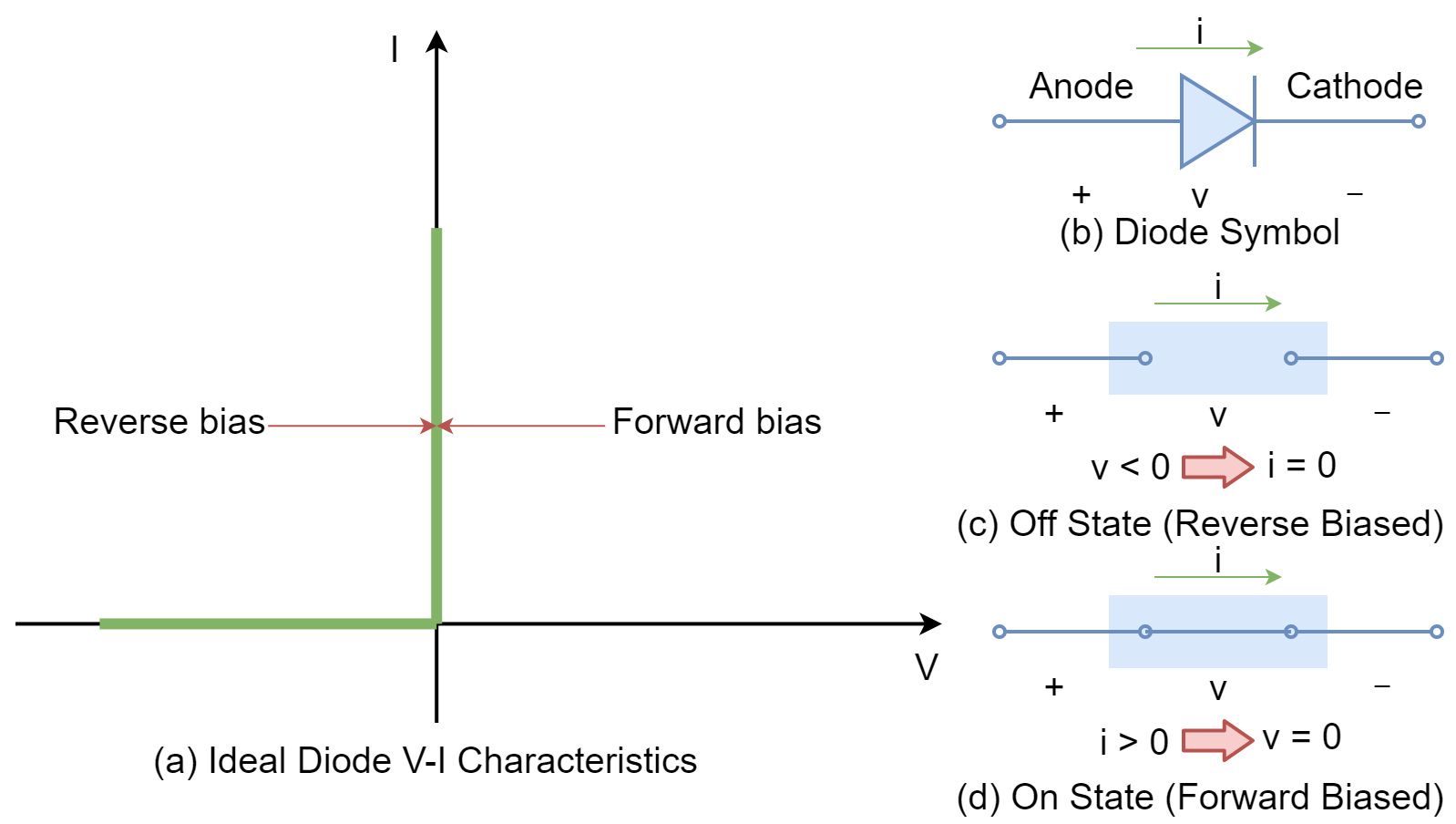
When a voltage source is connected to a diode in the way that anode is connected to (+) and the cathode is connected to (-) terminal of supply then the diode is said to be operating in a forward direction (forward-biased). The reversal of supply terminals, makes the diode operate in the reverse direction. In a forward-biased ideal diode, the diode/ switch becomes closed and maximum current starts to flow with the fraction of voltage applied. In the reverse direction, the ideal diode operates in an open state, and no current flows irrespective of the applied voltage. The ideal diode describes the states of switch i.e. ON & OFF under forward and reverse bias.
Real Diode
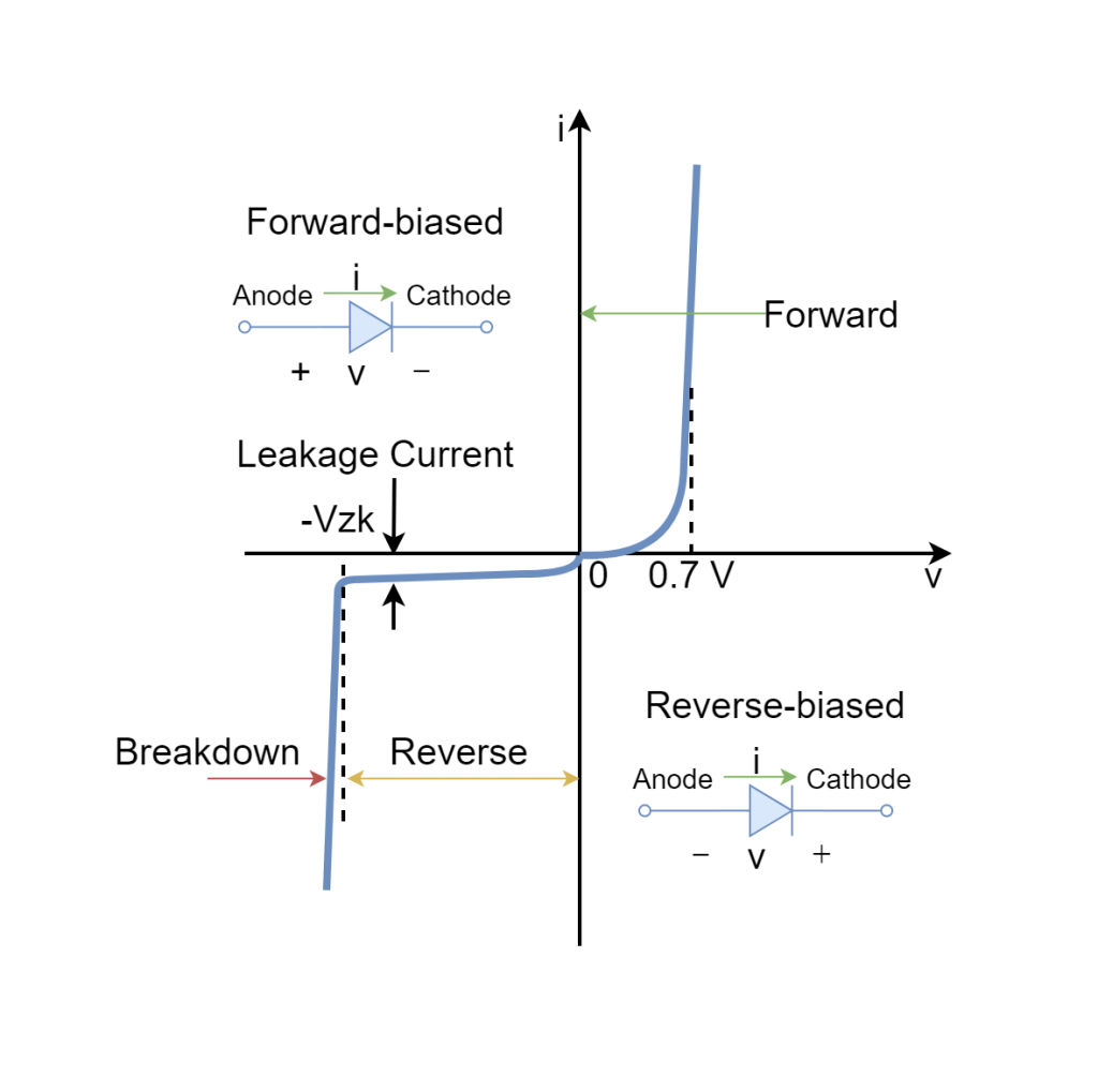
In a real diode, the V-I characteristics are more complex compared to the ideal diode and depend on many factors such as doping level, operating temperature, physical size, and semiconductors used in fabrication. The V-I characteristics of a real diode can be divided into three regions: forward, reverse, and breakdown. The V-I characteristics of a typical diode are depicted hereunder:
Forward-biased Region
Under the forward biasing condition, the diode does not conduct until a certain level of voltage is applied. The level of voltage that permits the flow of current depends on the barrier voltage of that specific PN junction. Once the level of voltage applied crosses the barrier voltage, the PN junction of the diode allows the current to flow through it. The relationship between V & I is exponential (non-linear) and is depicted in the above figure. In the forward region, the current increases rapidly with the little increase in voltage, and as such a current limiting resistance is recommended to be used in the diode to avoid going beyond the maximum power dissipation of the diode.
Reverse-biased Region
When the diode is reverse biased, a negligible amount of current flows which is specifically as drift current. This current is dependent on the temperature and is due to minority carriers. The drift current is of very low magnitude and neglected to allow supposition that no current flows through the reverse-biased diode. The diode is said to be in an off state until the breakdown region is reached. It is good practice to add a series resistor to the reverse-biased diode as the diode under this state is open and all of the voltage will appear across the diode under the absence of the series resistor. The resistor, in series with the reverse-biased diode, shares the voltage drop and protects the diode.
Breakdown Region
The diode resists the flow of current in reverse biasing until a certain level of voltage is achieved i.e. breakdown voltage. The current flow is similar to forward-biased current but in opposite direction and under different phenomena. In this region, the diode does not get damaged as long as the power dissipation rating of the diode has not been compromised. Therefore, it is always a good practice to add a series resistor to the diode.
Types and Usages
The signal diodes are typically used for signaling, switching, and for processing of information. The signal diodes can pass high-frequency signals and allow currents up to 150 mA leading to a smaller size. They are mostly used in digital logics, wave clipping, television and radio circuits, etc.
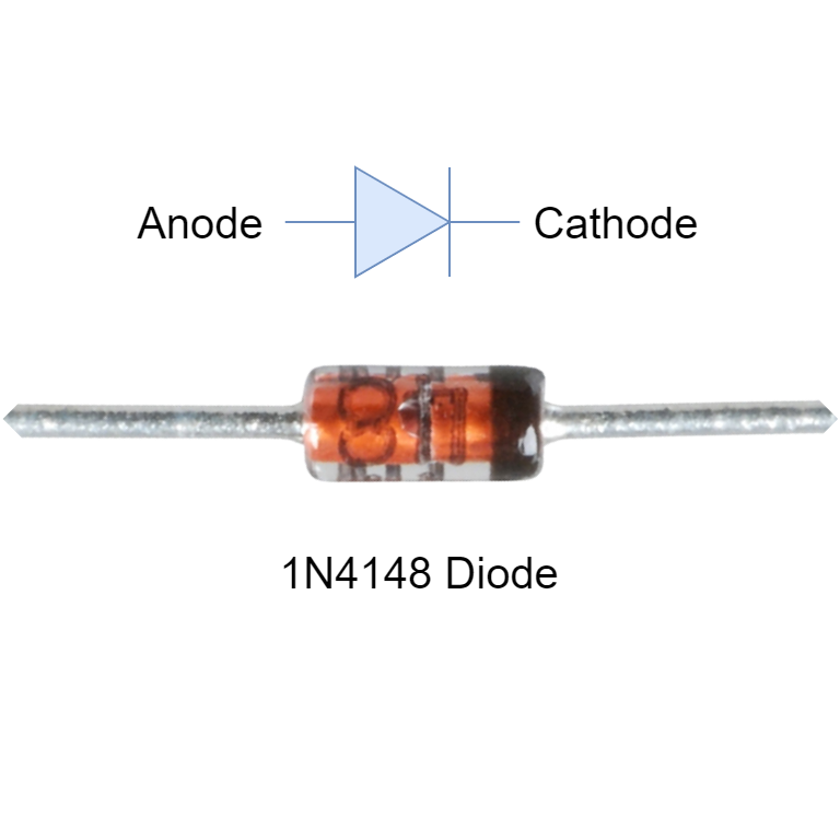
The diodes usually carry a marking to identify the cathode terminal in order to place them correctly in the circuit. Commercially available diode (1N4148) along with its cathode marking is shown in figure (3).
The semiconductor material used in the fabrication of diode contributes certain properties:
Silicon Signal Diodes
- Low forward resistance
- High reverse resistance
- Junction voltage drop around 0.6 to 0.7 V
- High forward current and reverse voltage
Germanium Signal Diodes
- High forward resistance
- Low reverse resistance
- Junction voltage drop around 0.2 to 0.3 V
- Low forward current and reverse voltage
Signal Diode Specifications
There are many variants of signal diodes that are commercially available and the manufacturing process of signal diodes induces different specifications & properties to sustain under varying conditions & applications. The manufacturers supply datasheets of signal diodes to allow engineers to select them according to their requirements/ applications. The most important ratings/ specifications of signal diodes are as follow:
Total Power Dissipation (PDMAX)
It indicates the maximum power that can be dissipated when the diode is forward biased. The diode offers some resistance due to the PN junction and drops certain voltage across the diode. The multiplication of voltage drop across the diode and current passing through the diode gives power dissipation. Power dissipation above the maximum rated value can damage the signal diode and as such should be avoided by restraining the power dissipation within the limits.
Maximum Forward Current (IFMAX)
It is the maximum allowable forward current through the signal diode. The PN junction of the signal diode offers resistance and the current passing through resistance produces heat. The heat increases with the increase in current and may cause thermal overload/ failure of the signal diode. The signal diode has limitations in forwarding flow of current and to remain under the limit a series resistor is used. For power diodes, the heat sinks are used to reduce the temperature as well.
Peak Inverse Voltage (PIV)
It is the maximum peak reverse voltage that can be applied to a signal diode. It is to ascertain that the signal diode does not enter into the breakdown region when operated at this voltage. This rating is considered when the diode is operated in reverse conditions i.e. freewheel diodes or rectifier diodes.
Maximum Operating Temperature
This is relevant to the thermal stability of the diode and the PN junction of the diode heats up due to the flow of current. The rising temperature can deteriorate the anatomy of the diode and should be avoided by considering maximum operating temperature besides power dissipation & forward current. The ratings of the signal diode are usually given at different ambient temperatures as they play a vital role in the stability of the diode.
Practical Applications
There are many applications of the signal diode in low power and high-frequency circuits involving wave-shaping, clipping, protection, and switching, etc. A few of them are explained below:
The Rectifier
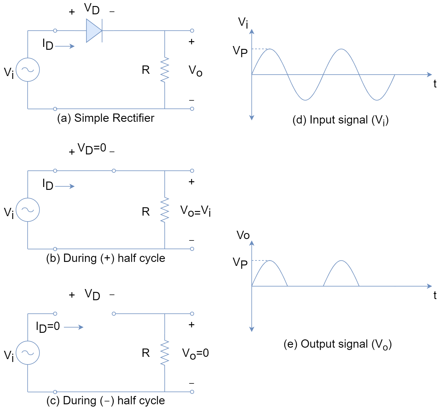
When an alternating signal (sinusoidal) is applied to a signal diode then it alternates its state in-between forward (on) and reverse (off) regions. This effectively makes the signal diode conduct in the first half-cycle and not conduct in the second half-cycle. The states of diodes in forward and reverse biasing are shown in figure (4). The signal diode as a rectifier is used only in low power circuits and for high power circuits, a rectifier or power diode is used.
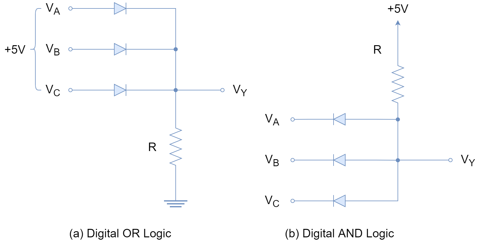
Digital Logic Gates
Another application of signal diode is in digital circuits for the implementation of logic. The following figure is framed on the basis that zero (0) voltage corresponds to logic zero (0) and +5 V to logic one (1). In part (a) of the figure (5), OR logic is implemented and any of three inputs [VA, VB or VC] gives VY = +5 V (logic 1). For logic zero (0) all of the inputs need to be at 0 V to turn off all the diodes.
Y = A + B + C
In part (b) of figure (5), AND logic is implemented, and to give logic one (+5 V) all of the inputs/ diodes [VA, VB & VC] need to be turned off. When any of the diodes is conducting (on) then it effectively makes the output VY = 0.
Y = A · B · C
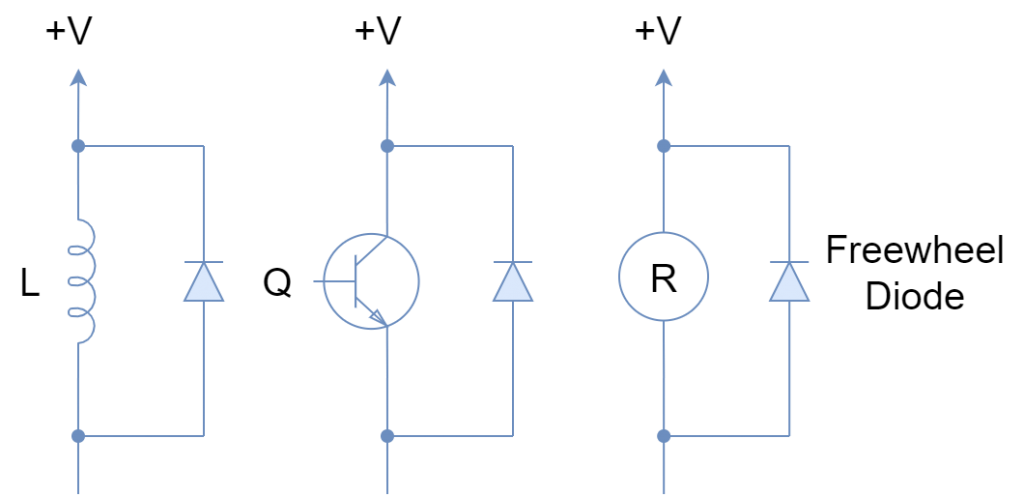
Freewheel Diodes
The signal diodes can be used to protect delicate components from voltage spikes or transients. These voltage spikes or transients are produced due to the fast switching of devices or changing the state of energy storing elements. The signal diode is placed in a reverse biasing state in parallel to the device that requires protection. Such position of a diode in circuit names it “Free Wheeling Diode” or “Fly Wheel Diode”. In the following figure (6), a few freewheel applications of the diode are shown. During on state of the device, the freewheel diode is reverse biased and all of the current flows through the device. As soon as the device turns off, the reverse voltage produced in the inductor makes the freewheel diode forward biased and all of the energy is suppressed through the diode. Similarly, in semiconductors, the freewheel diode protects sensitive components from sudden and accidental reverse voltages.
Conclusion
- The signal diode acts as a switching device alternating between ON & OFF states.
- In a forward-biased diode, the current flow is due to majority carriers i.e. diffusion current.
- In a reverse-biased diode before the breakdown, the negligible amount of current flows called drift current or saturation current and is majorly dependent on the temperature.
- In reverse-biased diode on achieving breakdown, the significant amount of reverse current flows and that may damage the diode under the absence of protections.
- The signal diodes are typically used in low-power and high-frequency circuits.
- The applications include rectification, digital logic and freewheeling, etc.


