Hero999
-
Posts
2,433 -
Joined
-
Last visited
-
Days Won
1
Content Type
Profiles
Forums
Events
Everything posted by Hero999
-
Unfortunately the original thread is missing because the server crashed awhile ago causing all threads posted before February 2009 to disappear.
-
http://www.maxamps.com/Power-Supply-30A.htm http://parts.digikey.com/1/parts/1207857-pwr-sup-12v-50a-sng-output-sws60012.html http://www.mpja.com/prodinfo.asp?number=16751+PS
-
That's not completely true, it will turn on a little bit, just not enough to power the LEDs, they might glow dimly. I have a couple of possible solutions: 1) Replace the BD140 with a P-channel MOSFET, remove the 1k resistor and connect a 10k resistor across the bridge rectifier. 2) Omit the 1k resistor and replace the BD140 with a Sziklai pair, the rest of the circuit should leak enough current to turn it on, if in doubt connect a 3k9 resistor across the rectifier As shown the LEDs will draw about 25mA per diode, if fix #1 is used which might be too much, I'd recommend increasing the series resistors. If fix #2 is used, the current will only be 19mA per diode so the resistors can stay as it.
-

Want a 4400uF 50WVDC Capacitor
Hero999 replied to RFamateur's topic in Sell/Buy electronics - Job offer/requests
You won't find a 4400μF capacitor because it isn't a standard value. Capacitors are only normally made in E6 values (E12 if you're lucky), look up "preferred value' on Wikipedia for more information. Just use 4700μF, the chances are it's just a typographical error. -
There are hundreds of projects on this site. Please provide a link to the one you're talking about.
-
How are we supposed to know when you haven't provided the schematic?
-
Did you use the same transistors or did you replace them all? It sounds like there's a problem with one of the transistors. Your speaker is quite old, Yugoslavia no longer exists. ;D
-
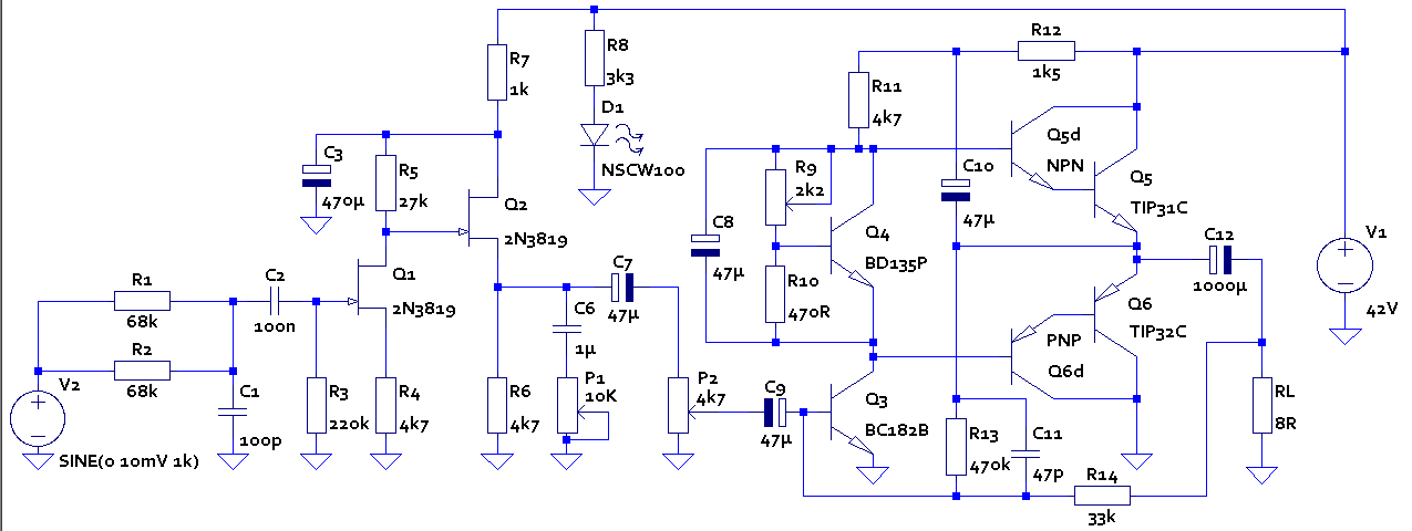
The voltages are all referenced to 0V. To measure the voltage between two points, simply subtract the voltage at one point from another. It's probably easier to use a calculator but LTSpice can do it for you. For example with this circuit: Set the simulation command to transient analysis and run the simulation command. Click Q5d's base to get the base voltage. With the schematic window selected wave the mouse cursor over Q5's emitter, the cursor will change to a red probe, note the net name displayed in the bottom left hand side of the screen 'Click to plot V(N009)' Right click on the graph legend 'V(n005)', a dialogue box will appear. In the text box, append '- V(n009)' (with out the ') to the text, it should look like 'V(n005)-V(n009)' Don't worry about whether it's upper or lower case, SPICE is case insensitive. Click OK. The line on the graph will be equal to the voltage between the base and emitter, again you can click on the graph legend to get the voltage at any point in time. In this example, with the input set to zero Q5(VBE) = 1.24709V, note that because Q5 is really made from Q5 and Q5d, the base emitter voltage has been measured across them both.
-
Then the problem is with the Li-ion battery. Does it sometimes work, then suddenly stop working? It's probably a loose connection. Try moving the wires around or tapping it to confirm this. Check all connections, resolder any bad joints and tighten any loose terminal screws.
-
Capacitors should always be discharged before assembling a circuit. Connecting charged capacitors to a circuit is always a bad idea.
-
You'll probably find that just sending a 40kHz sound out through one transducer and monitoring the intensity of the reflected pulse, will give unpredictable results. The intensity of the refection will depend as much on the shape object and its composition than its distance. For example you have two objects, one made of foam and the other from steel: the steel object is reflects sound and the foam object absorbs sound. If you placed both objects the same distance away from the amplifier proximity sensor, the absorbent object will appear to be a much further away than the reflective object. This is why you need to measure the amount of time it takes for a pulse to be reflected off an object to gauge its distance, simply measuring the intensity of the reflection won't work. As I said earlier, if you want accuracy you'll need temperature compensation and for real accuracy air pressure compensation, although this is probably overkill for what you want.
-
You've probably noticed that there is no C13 or transformer in the schematic. This is because, to make the simulation run faster, I've replaced them both with V1 which is set to 42V as it is the voltage you said is across C13. I assume you're talking about the DC voltage? There are two ways to get the voltage at a certain point. 1) Use the transient analysis, should be the default, and set the V2 to 0V and select run from the simulate menu. Now click on the node and a straight line will appear on the graph, if you click on the legend on the graph a cursor will appear, allowing you to read the exact voltage. 2) Use the 'calculate DC operating point' tool. Select 'Edit Simulation Command' from the simulation menu, click on the 'DC op pnt' tab, click 'ok', place the cursor anywhere on the schematic and click, you'll see a label '.op' appear, this is the simulation command. Select 'run' from the simulate menu, a list of voltages at all the nodes will appear, the trouble is that the nodes will have obscure names such as V(n006) unless you've names them using the label net tool. To turn a pot, right click on the symbol and edit the 'wiper=' setting, the number should be from 0 to 1 and represents the position of the wiper, for example 0.5 is half way along. LTSpice is not an interactive package so you'll need re-run the simulation every time you've made an adjustment. LTSpice is a very powerful simulation package, but it does have a steep learning curve if you don't have much experience with electronics or other simulation software.
-
If you're talking about EMC filtering then no, resonant filtering is no beneficial, it's harmful because tuned circuits can be excited leading amplification of certain frequencies. Resonant filtering is only used for tuning a circuit to a particular frequency, for example in a tuned radio receiver a capacitor is placed in parallel with an inductor to form a tuned circuit.
-
is there any type of sensor that . . .
Hero999 replied to vannic's topic in Electronic Projects Design/Ideas
Good idea, it shouldn't be hard to add a lower case 'r' for reverse. I think the idea is to mount the device to the underside of the gear stick. What about using an IR LED and an array of photo-transistors? Mount the LED on flexible cable and put the sensors underneath it. Ambient light shouldn't be a problem on the underside of the car so there shouldn't be any need for filtering or pulsing. -
I wouldn't buy a module that doesn't have a datasheet. How do you know it's FM? It looks like a remote control transmitter. Are you sure it has sufficient bandwidth for voice?
-
How much mW is a typical IR diodes used in TV remote?
Hero999 replied to DYORD's topic in Electronic Projects Design/Ideas
Looks good as long as you know that the maximum continuous forward current is 100mA which will typically output just 35mW so you'll need to use 200 to get the 7W of radient power you originally wanted. The half angle is only 17 -
You'll need to upgrade LTSpice's default transistor library. Back up the existing LTSpice/lib/cmp/standard.bjt Remove the .txt extension from the attachment and save it in the LTSpice/lib/cmp directory.. I've also included a picture of my LTSpice implementation of the circuit, not that Q5 and Q6 are drawn as two transistors because I couldn't find a Darlington model. standard.bjt.txt
-
Here's the LTSpice file, plus all the required libraries. Remove the .txt extension and make sure they're all in the same directory, alternatively copy the .sub file to LTSpice's lib/sub directory and the .asy to the lib/sym/Misc directory. 10W_Guitar_Amp.asc.txt potentiometer.sub.txt potentiometer_EU.asy..txt
-
To be picky, it's not the inductance that's the problem, it's the motor's inertia causing the high current surge. An inductor would draw a small current at first which would increase linearly until it's limited by the resistance. As this particular supply can source higher currents at lower voltages, you could start at a low voltage and increase it until the motor reaches full speed. Obviously the power supply needs to have an adequate power rating to drive the motor which I think is the issue here.
-
Traditionally most low to medium power high frequency power supplies (<1kW) are not resonant and use PWM to adjust the amount of power i.e. regulate the output current or voltage. More modern and higher powered SMPes, typically are resonant. The employ a technique known is zero voltage switching where the transistors are only turned on when the voltage across them is zero. Here's a link with more information. http://www.powerdesignindia.co.in/STATIC/PDF/200901/PDIOL_2009JAN21_PMNG_TA_01.pdf?SOURCES=DOWNLOAD
-
It's oscillating. An incandescent lamp is a non-linear load, when the filament is cold, its resistance will be very low, when the filament is hot, its resistance will be much higher. The amplifier is only designed to power a 4Ω to 8Ω speaker, connecting a lower impedance load, such as an incandescent lamp with a cold filament, could damage Q5 and Q6. If you want to test it without the speaker, use a 3.9Ω to 8.2Ω resistor as a dummy load, like I told you before.
-
Looking for a 30v varistor
Hero999 replied to james1586's topic in Sell/Buy electronics - Job offer/requests
Its a bit late now but did you consider using an equivalent? Surely you could have bought a different brand of varistor with a similar breakdown voltage and energy rating. -
Simulate it in LTSpice. That will give you the approximate voltages and currents you'll expect in different parts of the circuit. I'll post the files if you like.
-
It's pretty normal for a transformer to output a much higher voltage when lightly loaded and the mains is probably also on the high side. The circuit should be designed to account for this but this doesn't seem to be the case as the filter capacitor is specified for 35V, it should be 50V. The DC voltage across the filter capacitor should be about 42V.. I'll rerun the simulation with the DC voltage set to 42V and see what happens. EDIT: I've simulated it and it seems to work, R9 needed readjusting but it works. Of course this doesn't mean it'll work in real life but I don't see why not.
-
Looks good up until Q5 and Q6. That sounds right to me. Did you manage to stop it oscillating? If not then it's pointless trying to measure DC voltages because the AC could interfere with your meter causing it to generate inaccurate readings. Look at the schematic, rather than just assuming what you've been told is true. The voltage between Q5's collector and 0V should be equal to the DC supply voltage. The voltage between Q5's emitter and 0V should be approximately equal to half the supply voltage. I simulated it with a DC voltage of 30V and the voltage on Q5's emitter is 13.6V which is within 10% of the estimated value. I don't know what is wrong with your circuit, your VBE measurements of Q5 and Q6 suggest that they should both be off, yet the high quiescent current indicates they're both conducting too much and the emitter voltage of Q5 also suggests they're both conducting.