HarryA
-
Posts
453 -
Joined
-
Last visited
-
Days Won
24
Content Type
Profiles
Forums
Events
Everything posted by HarryA
-
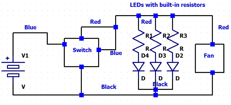
I believe this is what you need: push botton switch.asc push botton sw.xcf
-
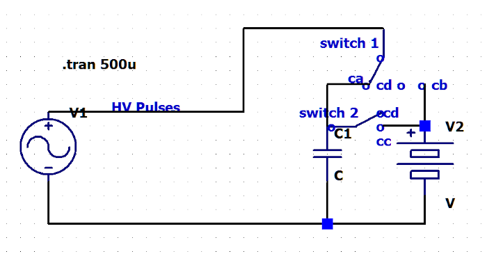
Is the action like this? I got to many cd's Are you comfortable using a micro-controller like an Arduino UNO? time: action switch 1 switch 2 0: hv pulses charge C1 at ca at cd S2's 1: C1 is charged to 24v at cd at cc 2: hv pulses applied to V at cb at cc 3: C1 drops to 17v at cd at cd S2's 4: hv pulses charge C1 at ca at cd S2's cycle repeats
-
What types of short period are you interested in? What divert times are you interested in? An inductor in series with the source and load would retard the current going out and when the magnetic field collapses there would be a back emf towards the source. A length of coaxial cable would form a delay line. If not terminated to match the cable at the load a pulse would be returned towards the source. see: analog delay line
-
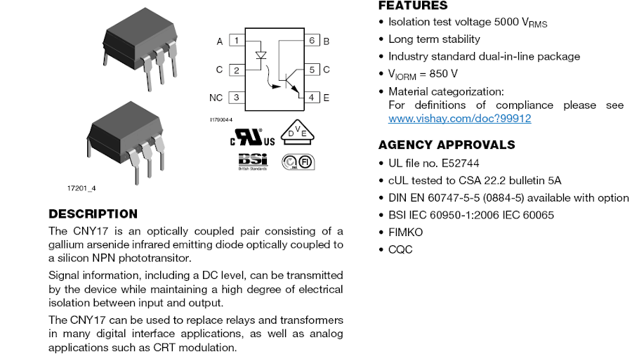
I used an optocoupler between an Arduino Uno and a mosfet at 350 volts for an capacitor discharge ignition circuit.
-
VARIAC
-
Multi-turn pots makes it slow to make adjustments. As Vellerman did not use them perhaps you could replace the pots with good ones like Allen-Bradley pots. Beware of the various tapers that pots have. Check Ebay for good prices on Allen-Bradley pots from US suppliers.
-
Are you using the information from Jaycar site? There is lot of information on their web site in Specifications and Articles. https://www.jaycar.com.au/atmega328p-mcu-ic-with-arduino-uno-bootloader-and-16mhz-crystal/p/ZZ8727 The manual is here: https://www.jaycar.com.au/medias/sys_master/images/images/9794372567070/ZZ8727-manualMain.pdf
-
 Forums like this one would be more useful for your questions. They have folks there that have a lot of combined experience. https://www.solarpaneltalk.com/
 -
What code book? And why do you care? Unplug the refrigerator and plug it into one of these. https://www.ebay.com/itm/293616232230?_trkparms=amclksrc%3DITM%26aid%3D1110018%26algo%3DHOMESPLICE.COMPLISTINGS%d%3APL_CLK|clp%3A2047675
-
As this was in response to a previous post that was removed I will replace with a joke: Wife texts husband on a cold winter morning: "Windows frozen, won't open "Husband texts back: "Gently pour some hot water over it and then gently tap edges with hammer." Wife texts back 10 minutes later: "Computer really messed up now."
-
I would think these 5 volt and 5 or 8 ampere power supplies would be useful for micro-controllers, etc. https://www.sciplus.com/8a-5vdc-power-supply-65520-p
-
If you are handy with a soldering iron you can get a push button switch with potentiometer on ebay. for example: https://www.ebay.com/itm/113927101102?hash=item1a86959aae:g:TyAAAOSw6ShdqKXJ&amdata=enc%3AAQAHAAAAsCTccvK8zt8P7ay7xO2JNnQVqK54hb11np% You would need to match the potentiometer on the switch with the one on the timer board. You could replace the potentiometer and switch on a timer board like this perhaps: https://www.amazon.com/Module-Adjustable-Timing-Switch-1-10sec/dp/B07SL5HBZ9/ref=sr_1_58?crid=3806JFZG2WCBO&keywords=time+delay+board&qid=1670774252&sprefix=time+delay+board%2Caps%2C129&sr=8-58 Look for one with the delay you need.
-
"Search for the power board for a Tektronix oscilloscope mod. TDS460. The P/N is PS1690 rev.A" In the future you may use https://translate.google.com/ There are a number of boards on ebay.com for the TDS460. You will have to scroll down to find them. See: https://www.ebay.com/sch/i.html?campid=5338192028&kw=TDS460&mkcid=1&mkrid=711-53200-19255-0&toolid=20004
-
Is Rolling Meadows, IL 60008 near you? see: https://www.solder.net/training-courses/bga-rework-training/ See for low key diy rework: https://www.instructables.com/BGA-rework/
-
You need to supply a link/url to the DXP software you are using. There are numerous software packages called DXP.
-
see: https://en.wikipedia.org/wiki/Button_cell for chemical composition of the CR2032 cell. The C tells you it is Lithium and Manganse Dioxide.
-
You have been well answered on the numerous forums you have posted this question on. I do not see anyway to post links now - Admin got sick of having to delete them?
-
I would think you would not need a converter given: "Discharge current is software and electronically regulated using a solid state switch and fan cooled electronic load" Why can't you get the energy/power by simply charging a capacitor over some time interval? Given work W = 1/2*C*V*V in joules. You may need to make allowance for the capacitor's ESR either charging or discharging. For others: Equivalent series resistance (ESR) describes losses associated with moving a charge through a capacitor. See: https://www.digikey.com/en/articles/simple-explanation-of-capacitor-esr
-
I would think shorting the output would kill the converter thus acting as a smokey fuse. The solar power folks use converters that supply a constant output for varying input voltages. One would like a converter that supplies say 5v as the capacitor discharges from say 12v to 7v. Perhaps this type: https://www.amazon.com/DEVMO-Adjustable-Converter-XL6009-Voltage/dp/B07SZQMKLW Also searching on the internet for "solar dc up down converter" will give you some useful information.
-
Try measuring the input resistance at the +Vin and -Vin. On the up/down converters I have they measure 400k to 2meg ohms. Perhaps comparing the two would be helpful. One has to expect failures from these inexpensive Chinese modules.
-
Perhaps one could use a dc to dc converter without loading the capacitor, thus not discharging it quickly? They made various types for various voltage combinations. See for example: https://www.amazon.com/Aceirmc-Current-Converter-Adjustable-Regulator/dp/B082XQC2DS among many. This subject comes up often on the internet; I see a Youtube video for replacing the battery in an automobile with capacitors; I need to look at that one. If that interest you I have a 12v to 5v converter I could try.
-
Any one has the TNETV1051EACLZDW datasheet?
HarryA replied to erinxie's topic in Datasheet/Parts requests
Yes they hide it well! Try: https://www.sierraic.com//buy_online/datasheet/TNETV1051EA or Ti directly. Good luck. -
PTC resettable Fuses problem
HarryA replied to joseph20480's topic in Electronic Projects Design/Ideas
Sorry they are beyond me. Why would one use a 3 amp fuse that trips at 6 amps? What does the 15 and 50 amps got to do with it? How would it allow current that high? Beware there are a lot of fake components out there. I got some ICs via Amazon.com lately they had the TI symbol on them but also "made in China" on them; never seen TI chips with that on them before. For other viewers: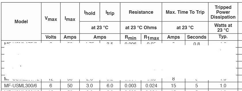
-
PTC resettable Fuses problem
HarryA replied to joseph20480's topic in Electronic Projects Design/Ideas
Time plays a big factor with PTCs; 26. Recovery time: The recovery time after PTC thermistor action should not exceed 60S. see: https://www.ntcsensors.com/Technical_parameters_of_PTC_resettable_fuse/#:~:text=Under limited conditions%2C the highest voltage that the,may be broken down and cannot be recovered. Also there is an interesting video that discusses PTCs here: https://www.youtube.com/watch?v=eeaqyD3ZYjI -
Hall Sensor Bypass for Coffee Grinder
HarryA replied to millicurie999's topic in Electronic Projects Design/Ideas
I think it would be a worth while experiment to increase the current flow in the motor circuit by say 200ma. From the next to the bottom table above that would push it above the 200 ma minimum for mild coffee but not put into the 800ma maximum. One would need to find the motor voltage in order to calculate the required added shunt resistor (across the motor terminals. I gather the beans never hang up within the machine so that the flow to the grinder is interrupted.