help with IR2110 chips

Alec_t

Jul 7, 2015
3,817
Joined
Jul 7, 2015
Messages
3,817
If you are switching the MOSFETs at only 50Hz they are unlikely to overheat.
Even at 50Hz I think there is going to be a fair amount of EMI generated by switching harmonics, because of those wire lengths and board layout.
Trying to switch them at tens or hundreds of kHz (typical inverter frequencies) would make the wire lengths and board layout a definite problem.
 

Maglatron

Jul 12, 2023
2,025
Joined
Jul 12, 2023
Messages
2,025
If you are switching the MOSFETs at only 50Hz they are unlikely to overheat.
Even at 50Hz I think there is going to be a fair amount of EMI generated by switching harmonics, because of those wire lengths and board layout.
Trying to switch them at tens or hundreds of kHz (typical inverter frequencies) would make the wire lengths and board layout a definite problem.
But it's okay in my situation? I suppose there is only one way to find out I could try and cut down the wire lengths to a minimum
gut tells me it will be absolutely fine!
 

Maglatron

Jul 12, 2023
2,025
Joined
Jul 12, 2023
Messages
2,025
now this sorry for all the quotes I'm just trying to determine if this is this:

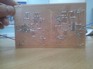
also included pic of back side of the board!!

I do PCB layouts for pay.
And I do the routing mainly by hand. So much more than 5 mins.

Yes, they are called protoboard. I know them since the 1970ies. That also was the time when they got their name.
And at that time they did a good job. ICs were slow, no WiFi and other HF around. No other devices around to get distrubed by the prototype.

But technology has advanced. (Protoboards not). IC´s are faster now .. no matter whether you run them only on 50Hz, the edges are fast and distribute a lot of HF noise.
Also they now react much faster on input signals ... also unwanted input signals, like WiFi, capacitively coupled signals, inductively coupled signals, ground bounce and so on.

In the 1970ies we had UKW in the 100MHz range with "critical trace lengths" of almost a meter.
And since the traces on the protoboard are much shorter ... they did not really work as transmitting antenna nor as receiving antenna.

Now that every IC has rise and fall times in the sub (or low) nanoseconds, the resulting frequency is in the 10s of GHz (mind: overtones caused by fast edges)
The critical trace length now shifts down to below some centimeters. Thus now the traces of the protoboard act as good antennas! .. even if you shorten them.

Again: this has nothing to do with your 50Hz switching frequency ... it´s only because ICs nowadays are much faster. And other HF sources are around.

***
In the 1970ies the signals were slow, this also means that for a signal on a trace with 10cm ... was considered to have the same signal (voltage) at both ends.
This is not true anymore. Your GND traces of 5cm in length (or even longer) may have a difference of several volts from one end to the other. Surely only for a short time, but due to the increase speed the ICs may react on this. It is likely to causes false trigger, ringing, oscillation, increased heating, malfunction, high voltage spikes, destruction.... in worst case explosion and fire.

***
PROTOTYPING.
Rapid prototyping is a common phrase today due to the availability of 3D printers.
Now if I 3D print a plastics prototype clamp for a bungee rope. Would you use this prototype for testing ... and jump?
I don´t think so. A prototype has several functions .. but also limitiations.

The 3D print bungee rope clamp may be use for photograph, for size considerations, for esthetic design considerations ... but it will not be fully functional.
The stability simply is too low for a real test.
The same is true for a protoboard and a switching power application. It is not suitable for functional testing. Even with no load.

***

I don´t say that your design does not work at all. It may work ... somehow. But maybe .. not at all.
But I can say it will not give any reliable results. You will gain not much information from this test setup.
You may connect a scope at it .... but if you compare the signal with what you "expect" or how the signal looks on a suitable design ... they will be so much different.
And even if it runs once .. it does not mean it runs a second time.

It´s like diving with a non certified Titan submarine. One can ignore the warnings of engineers, but one can not ignore physics.
****

All this has nothing to do with being disrespectful nor discouraging you from doing electronics.
I´m not here to annoy you. I´m here to tell you how electronics / physics works and what to care for.
--> I can only recommend to do it step by step.
--> And just want to warn you not to be surprised if it does not do what you expect it to do.


what do you recon Mr Alec_t please?
 

Attachments

  • DSCF0403.JPG
    DSCF0403.JPG
    305.7 KB · Views: 2

bertus

Moderator
Nov 8, 2019
3,837
Joined
Nov 8, 2019
Messages
3,837
Hello,

For planning of the board you could also use VeroRoute:

As said keep the wiring as short as possible.
Also the placing of the components will help to make the board more compact.

Bertus
 

Maglatron

Jul 12, 2023
2,025
Joined
Jul 12, 2023
Messages
2,025
the guy is trying to sell his services for £300 ne'er mate I'm going to look at veroroute now ! he's a hell of a salesman but I can't afford that the whole point of doing it DIY was to save money!
 
Last edited:

Maglatron

Jul 12, 2023
2,025
Joined
Jul 12, 2023
Messages
2,025
okay VeroRoute is a PCB layout program!!! thanks Mr Bertus
 
Last edited:

Maglatron

Jul 12, 2023
2,025
Joined
Jul 12, 2023
Messages
2,025
Hello,

For planning of the board you could also use VeroRoute:

As said keep the wiring as short as possible.
Also the placing of the components will help to make the board more compact.

Bertus
do you want to give it a bash?? I would so so so appreciate it if you could, don't like asking but I put my best in to making that circuit, I don't think it's that bad but any help welcomed!! never mind, I'll just get on with it! :D
 
Last edited:

Maglatron

Jul 12, 2023
2,025
Joined
Jul 12, 2023
Messages
2,025
ok, on it, learning VeroRoute, but remember this is just a prototype
 

Maglatron

Jul 12, 2023
2,025
Joined
Jul 12, 2023
Messages
2,025
I am more familiar with PCB wizard, anyone have it because my internet does not permit its download maybe split the file and upload please, I would be very grateful, thanks guys I really need it!!
 
Last edited:

bertus

Moderator
Nov 8, 2019
3,837
Joined
Nov 8, 2019
Messages
3,837
Hello,

Did you try other download sits?

On the official site I see it needs a licence.
The cheapest licence is 39.99 USD.

Bertus
 

bertus

Moderator
Nov 8, 2019
3,837
Joined
Nov 8, 2019
Messages
3,837
Hello,

That download is only a demonstration. It seems to be limited.

Bertus
 

Maglatron

Jul 12, 2023
2,025
Joined
Jul 12, 2023
Messages
2,025
I see I will buy it when I get paid in 2 weeks
 
Last edited:

Maglatron

Jul 12, 2023
2,025
Joined
Jul 12, 2023
Messages
2,025
is there a way to double up the mosfets for more current and less heat if so can you modify this schematic please
 

Attachments

  • IR2110withLM7805.asc
    7.8 KB · Views: 2

Alec_t

Jul 7, 2015
3,817
Joined
Jul 7, 2015
Messages
3,817
is there a way to double up the mosfets for more current and less heat
I doubt the MOSFETs are limiting current significantly. The main limitation is due to coil inductance.
More current generates more heat, albeit distributed differently if you use more MOSFETs to share the load..
 

Maglatron

Jul 12, 2023
2,025
Joined
Jul 12, 2023
Messages
2,025
cool! so can you teach me/show me how to integrate another 4 mosfets please, thanks
 
Last edited:
Top