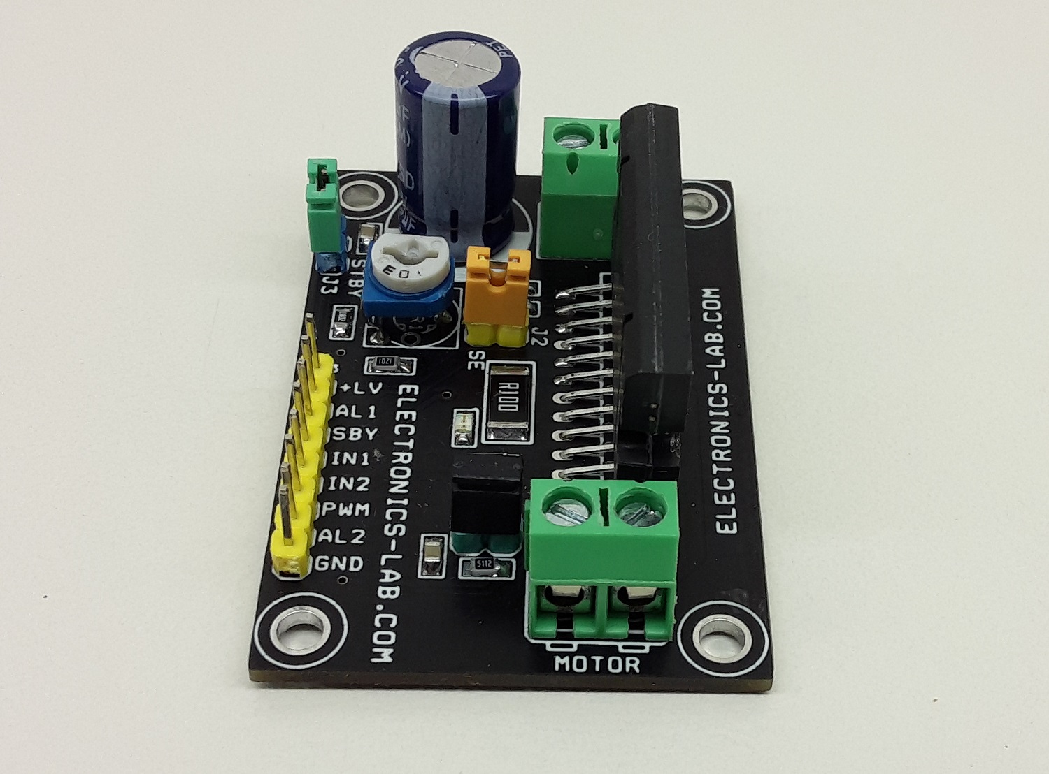
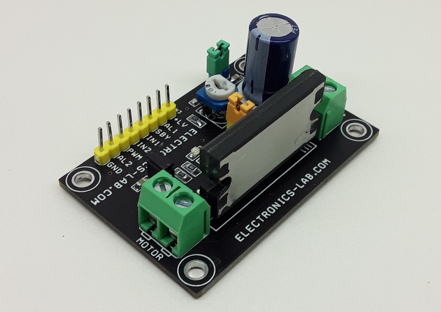
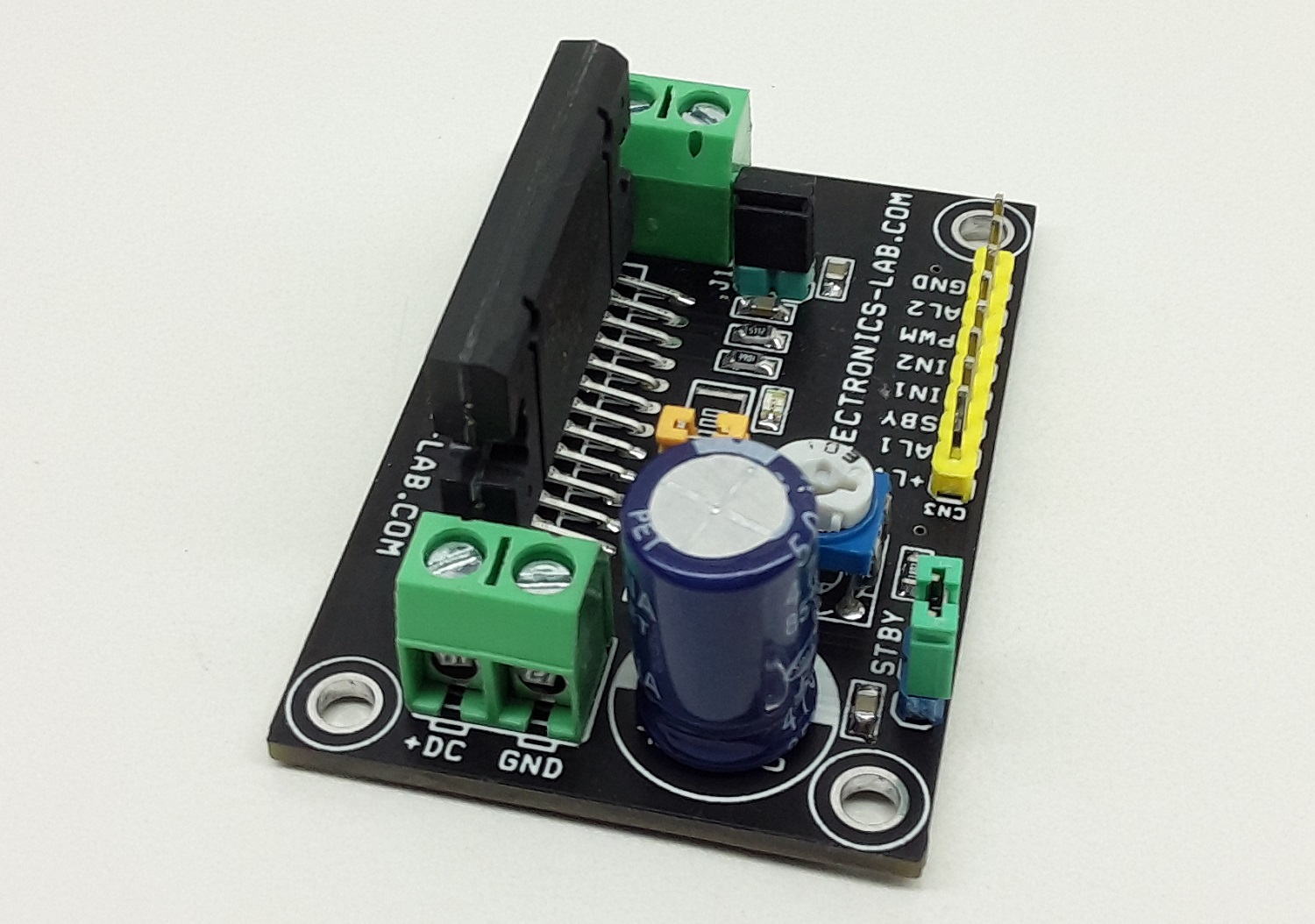
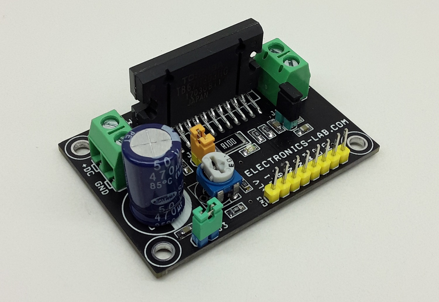
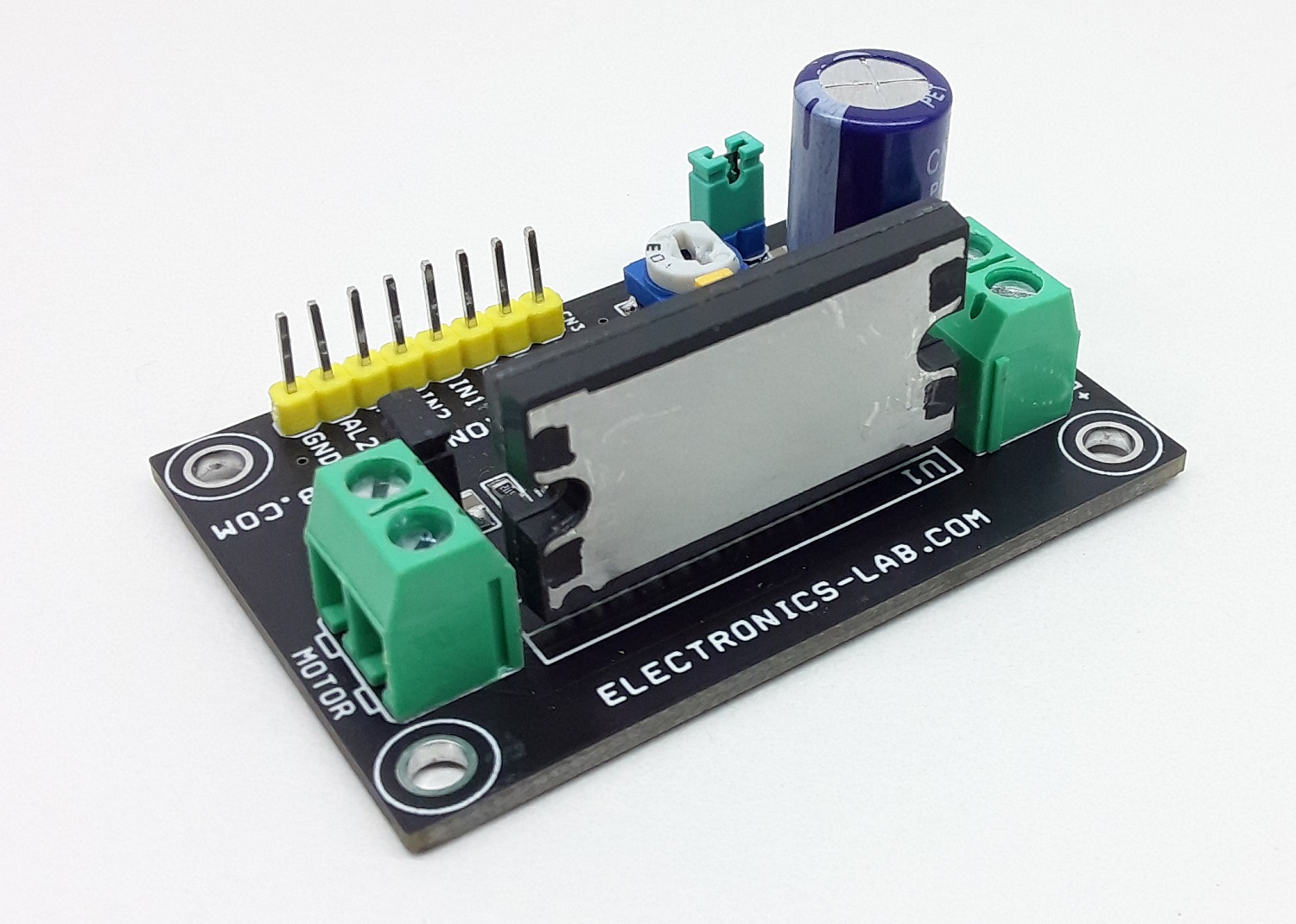
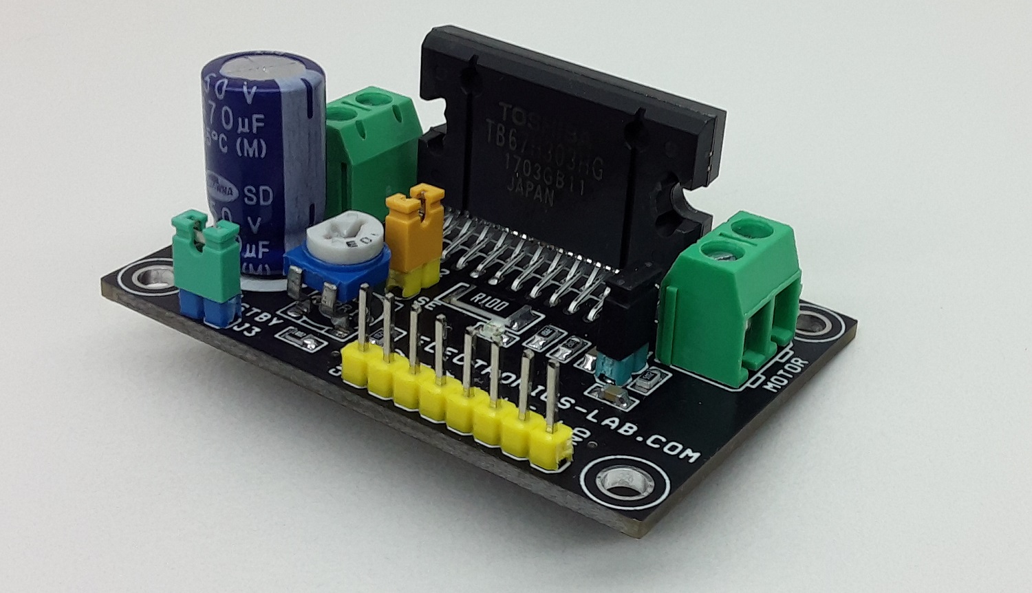
8A Brushed DC Motor Driver with Adjustable Constant Current, Direction Control, Brake Control, Speed Control
This is a very powerful brushed DC motor drive system in a small package with a few key features like adjustable constant current control, direction control, brake controls, Alert output, PWM for speed control etc. The project was built using a TB67H303HG chip which is a full-bridge driver IC for DC motor adopting MOS at output transistors. High-power and high-efficient drive are possible by adopting DMOS output driver with low-ON resistance and PWM drive. Refer to the datasheet of TB67H303HG for more information.
Features
- DC Motor 24V DC, (Range 8 to 40V DC)
- CW/CCW, Short Brake, Stop Function
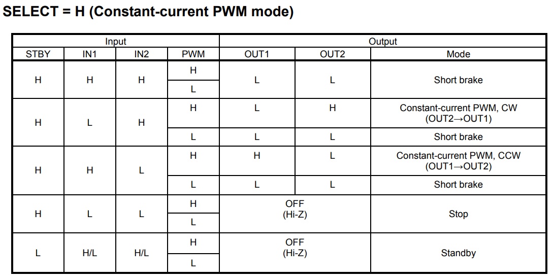
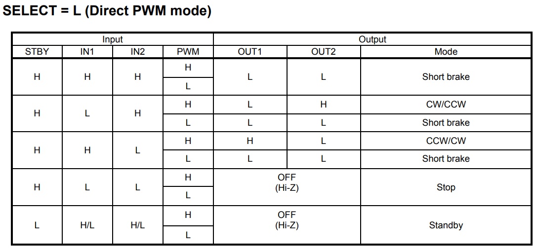
- PWM control (Direct PWM or Constant-current PWM drive)
- Standby Function
- Load 8.0 A (operating range, maximum value)
- On-Board Power LED D1
- PWM Frequency Input Up to 100Khz, Duty Cycle 50%
- PCB Dimensions 53.98 x 36.83 mm
The project has been designed for constant current mode however, this can be used as direct PWM mode with a few changes, explained below.
Selection of Constant Current Mode
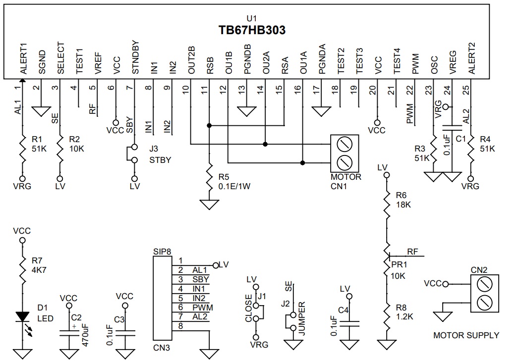
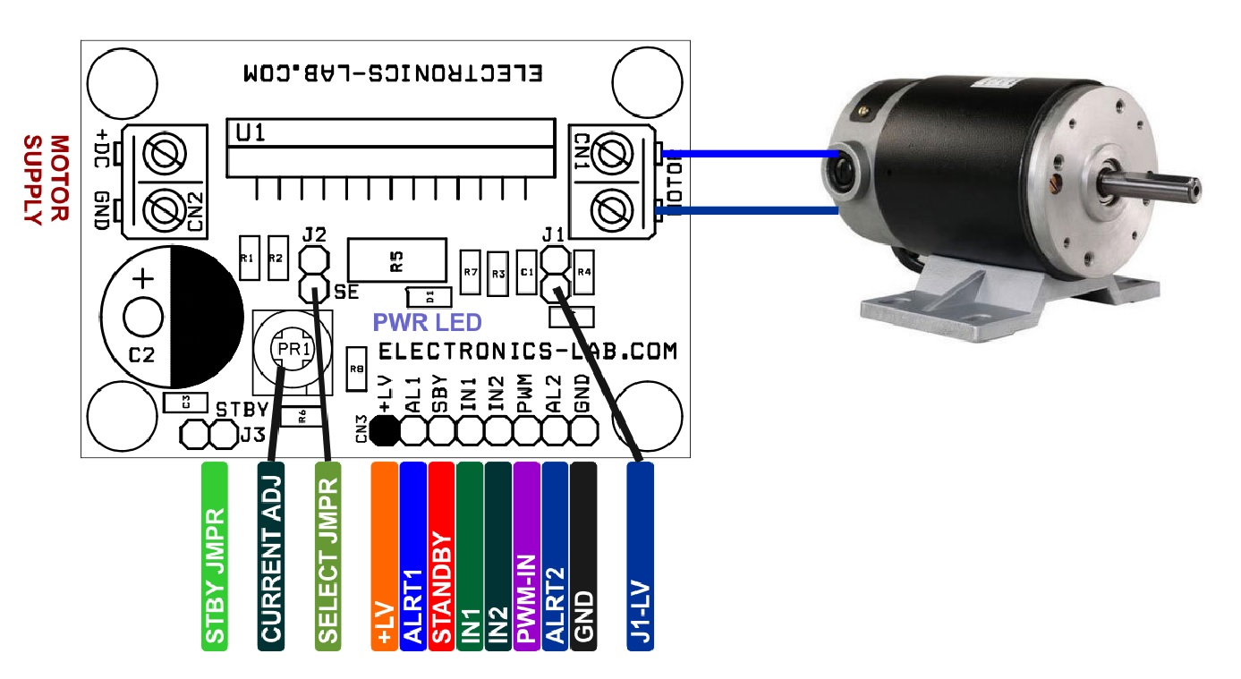
- Close The Jumper J3 for standby or Provide 3.3V or 5V to Standby Pin3 (SBY) of CN3
- Jumper Select J2 Open (Select Pin =High)
- Jumper J1 Close (Jumper Connects, VREF 5V and Logic Supply) Remove this Jumper for External Micro-Control Interface
- Trimmer Potentiometer PR1: Adjust the Constant Current (0.3V to 1.95V)
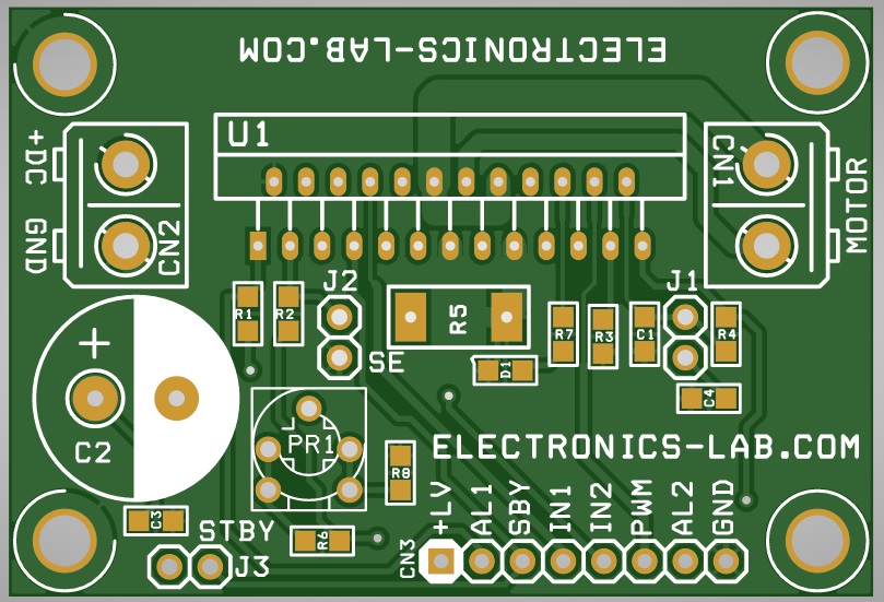
- CN1 Motor Connection
- CN2 DC Motor Supply 24V DC (Range 8 to 42V DC)
- Oscillator R3 51K Ohms provides 40Khz Chopping Frequency (30K Ohms=60Khz, 120K Ohms 20Khz)
- Alert 1 provides High Signal, Goes Low when ISD or TSD (CN3 Pin 2), ISD=Over Current, TSD=Thermal Shutdown
- Alert 2 When Motor Supply falls to 6.0V (typ.) and UVLO is enabled, output turns off and ALERT 2 outputs low. In case Motor supply falls below 6.0V (typ.), ALERT 2 outputs Hi-Z (High impedance). The operation returns from Standby mode when Vic rises 6.5V (typ.) or more. (CN3 Pin 7)
- Apply PWM Signal to PWM Pin 6 of CN3
ISD (Over current detection)
- Current that flows through output power MOSFETs are monitored individually. If over-current is detected in at least one of the eight output power MOSFETs, all output power MOSFETs are turned off. Masking term of 1μs or more (typ. when Rosc=51kΩ) should be provided in order to protect detection error by noise. ISD does not work during the masking term. The operation is not returned automatically. It is latched. This function is released by programming STBY H→L→H.
Selection Direct PWM mode with few changes
- Pull Down Select Pin Low by Closing the Jumper J2
- Replace Shunt Resistor R5 with 0 Ohms or use wire to shorth this resistor
- Jumper J1 Close (Jumper J1 Short)
- Pull Down VREF Pin, Do Not Populate R6, R8 0 Ohms, Turn Trimmer Pot to Minimum to zero or short two terminals so VREF pin is connected to GND
The motor rotation speed is controllable by the PWM input sent through the PWM pin 6 CN3. It is also possible to control the motor rotation speed by sending in the PWM signal through not the PWM pin but the IN1 and IN2 pins. When the motor drive is controlled by the PWM input, the TB67H303HG repeats operating in Normal Operation mode and Short Brake mode alternately. For preventing the shoot-through current in the output circuit caused by the upper and lower power transistors being turned on simultaneously, the dead time is internally generated at the time the upper and lower power transistors switch between on and off. This eliminates the need of inserting Off time externally; thus, the PWM control with synchronous rectification is enabled. Note that inserting Off time externally is not required on operation mode changes between CW and CCW, CW and Short Brake, and CCW and Short Brake because of the dead time generated internally.
Connections CN3
- Pin 1: LV Logic Supply Connected to VREG 5V Using Jumper J1 (Don’t Use) NC
- Pin 2: Alert 1 TSD/ISD Normally High, Goes Low when Alert Occurs
- Pin 3: IN1 Direction Change or Brake Operations (High or Low)
- Pin 4: IN2 Direction Change or Brake Operations (High or Low)
- Pin 5: PWM Input 3.3V or 5V TTL Signal (PWM Frequency Up to 100Khz Duty Cycle 50%)
- Pin6: GND
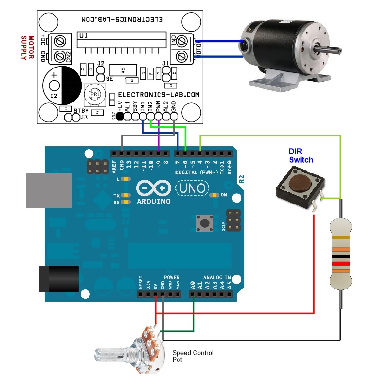
Arduino UNO Connection
Arduino test code is available as a download below. Please refer to the connection layout below to test the board.
Schematic
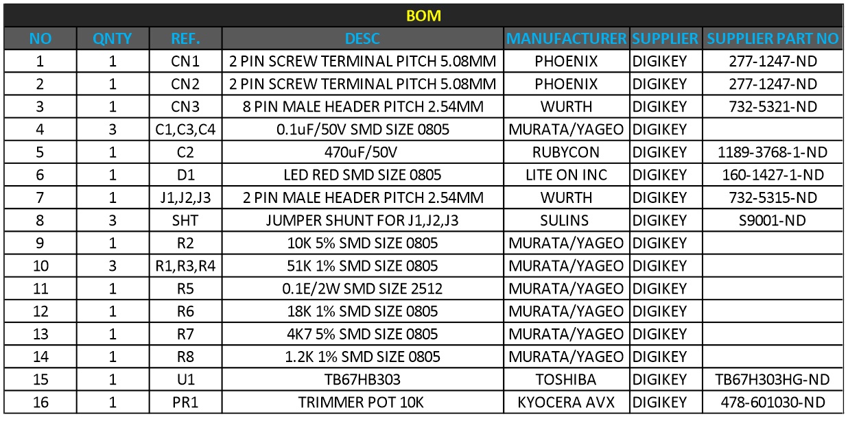
Parts List
| NO | QNTY | REF. | DESC | MANUFACTURER | SUPPLIER | PART NO |
|---|---|---|---|---|---|---|
| 1 | 1 | CN1 | 2 PIN SCREW TERMINAL PITCH 5.08MM | PHOENIX | DIGIKEY | 277-1247-ND |
| 2 | 1 | CN2 | 2 PIN SCREW TERMINAL PITCH 5.08MM | PHOENIX | DIGIKEY | 277-1247-ND |
| 3 | 1 | CN3 | 8 PIN MALE HEADER PITCH 2.54MM | WURTH | DIGIKEY | 732-5321-ND |
| 4 | 3 | C1,C3,C4 | 0.1uF/50V SMD SIZE 0805 | MURATA/YAGEO | DIGIKEY | |
| 5 | 1 | C2 | 470uF/50V | RUBYCON | DIGIKEY | 1189-3768-1-ND |
| 6 | 1 | D1 | LED RED SMD SIZE 0805 | LITE ON INC | DIGIKEY | 160-1427-1-ND |
| 7 | 1 | J1,J2,J3 | 2 PIN MALE HEADER PITCH 2.54MM | WURTH | DIGIKEY | 732-5315-ND |
| 8 | 3 | SHT | JUMPER SHUNT FOR J1,J2,J3 | SULINS | DIGIKEY | S9001-ND |
| 9 | 1 | R2 | 10K 5% SMD SIZE 0805 | MURATA/YAGEO | DIGIKEY | |
| 10 | 3 | R1,R3,R4 | 51K 1% SMD SIZE 0805 | MURATA/YAGEO | DIGIKEY | |
| 11 | 1 | R5 | 0.1E/2W SMD SIZE 2512 | MURATA/YAGEO | DIGIKEY | |
| 12 | 1 | R6 | 18K 1% SMD SIZE 0805 | MURATA/YAGEO | DIGIKEY | |
| 13 | 1 | R7 | 4K7 5% SMD SIZE 0805 | MURATA/YAGEO | DIGIKEY | |
| 14 | 1 | R8 | 1.2K 1% SMD SIZE 0805 | MURATA/YAGEO | DIGIKEY | |
| 15 | 1 | U1 | TB67HB303 | TOSHIBA | DIGIKEY | TB67H303HG-ND |
| 16 | 1 | PR1 | TRIMMER POT 10K | KYOCERA AVX | DIGIKEY | 478-601030-ND |
Connections
Truth Tables
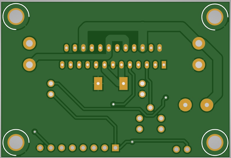
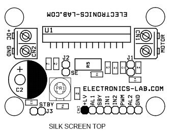
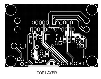
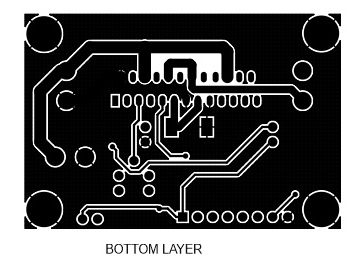
Gerber View
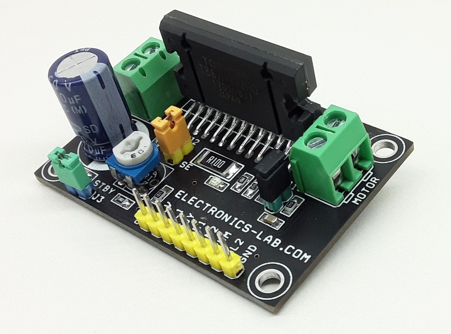
Photos
Video
TB67H303HG Datasheet
PCB