Analog To Digital Conversion – Binary Encoding
Introduction In the first part of this article, we considered the two main stages of a PCM (Pulse Code Modulation) system as the widespread A/D (Analog to Digital Conversion) method and we saw how a continuous signal can be sampled in time and then quantized to limited integer levels in amplitude. The quantum levels are related to a key number of ‘n’ by an exponential relation and the quantized amplitudes grow between minimum level (0) and maximum of (2n -1).
Introduction
In the first part of this article, we considered the two main stages of a PCM (Pulse Code Modulation) system as the widespread A/D (Analog to Digital Conversion) method and we saw how a continuous signal can be sampled in time and then quantized to limited integer levels in amplitude. The quantum levels are related to a key number of ‘n’ by an exponential relation and the quantized amplitudes grow between minimum level (0) and maximum of (2n -1).
Now we can see the process of producing digital signals from the quantized discrete signal by the third stage of the PCM system.
Binary Encoding Stage
After each sample is quantized, the encoder replaces quantized samples with unique digital code words. Generally, a code word can represent a number, a character, or an analog variable. The most usable code words are binary codes.
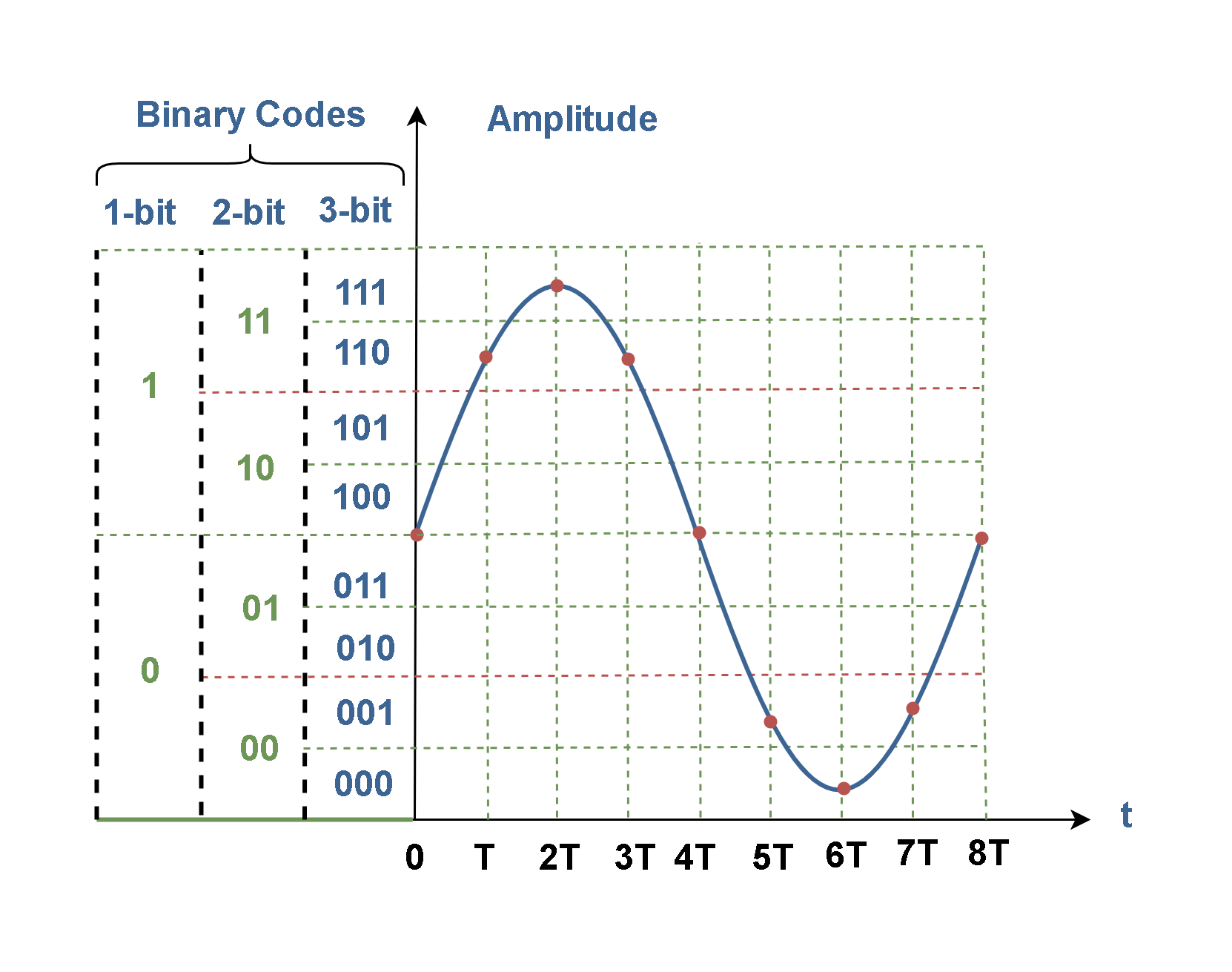
Figure 1 shows that each sample can be changed to an n-bit code word in the binary encoding stage. The purpose of this encoder is to assign a unique binary code to each discrete sample at the input. Hence, it encodes the quantized data from 2n possible states into an n-bit code. The binary codebook performs like a mapping table to relate input data to output codes. It defines each discrete value at the input is converted to what code at the output of this stage.
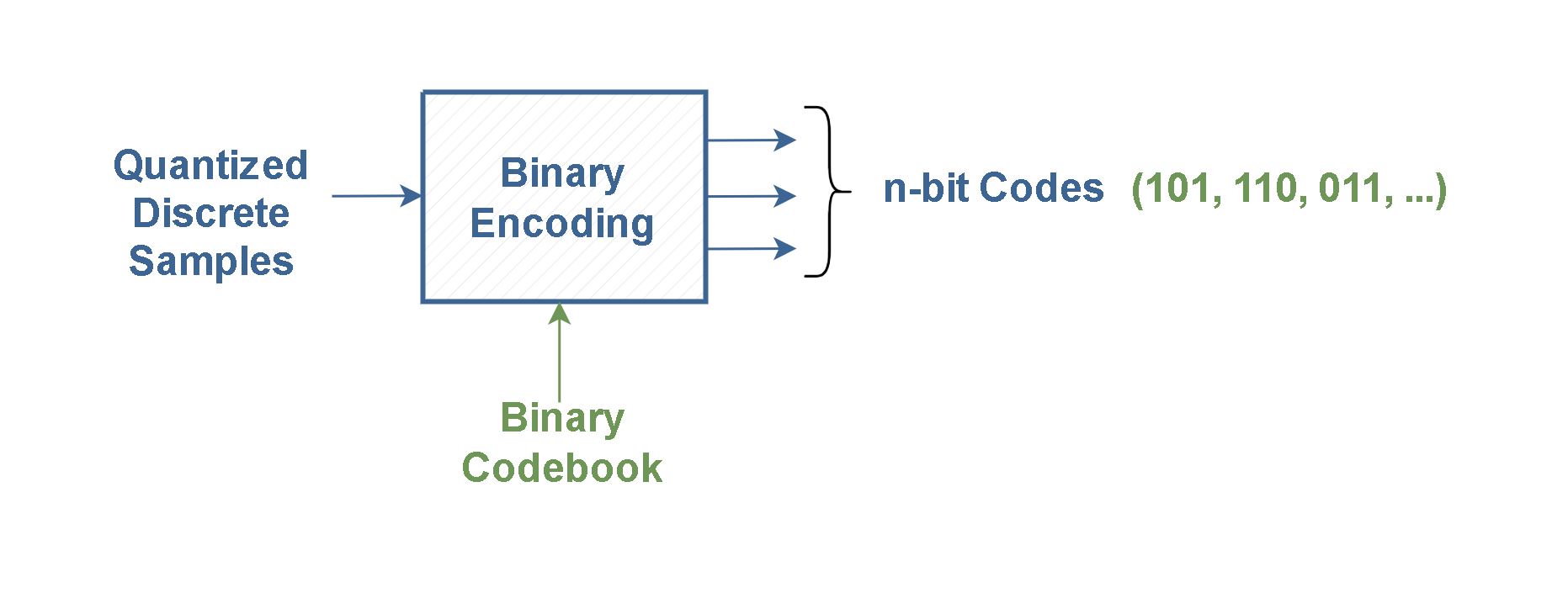
Figure 2 shows the results of A/D conversion on the analog signal v(t) in our previous example waveform after applying of the binary encoding stage.
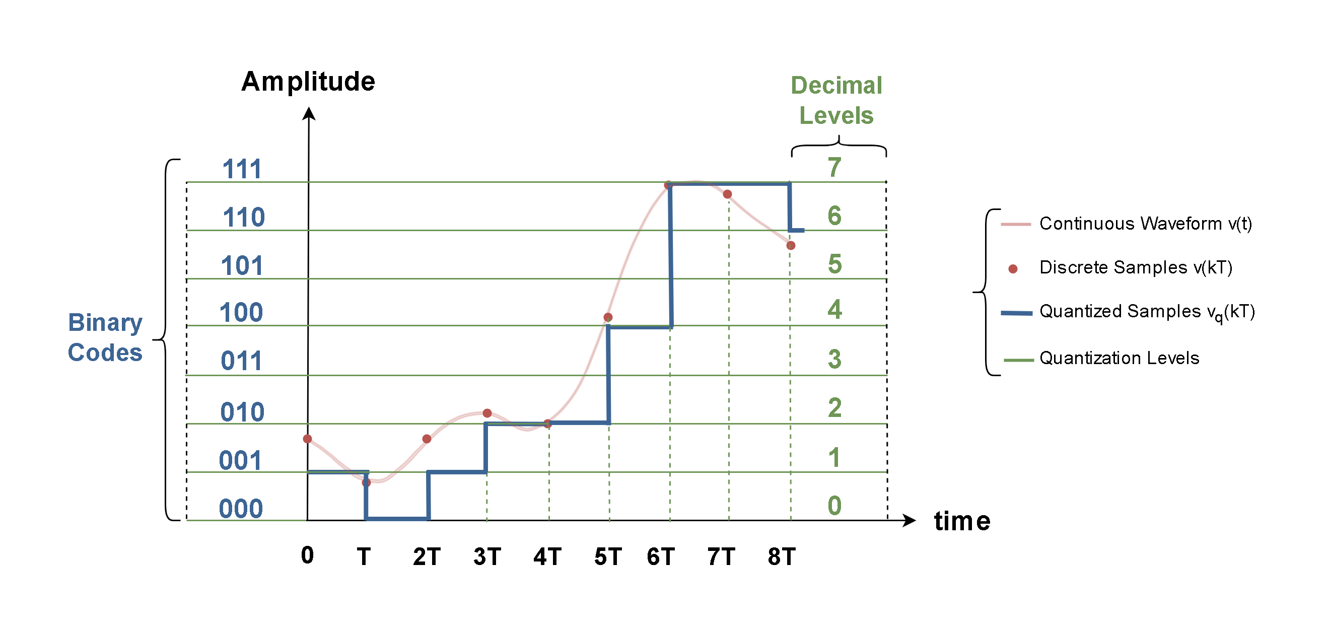
Figure 2 describes how the continuous waveform v(t) is sampled and changed to v(kT) samples at first and then, these discrete samples are quantized to 8 equal levels and changed to vq(t) waveform; whereas each quantization level has been assigned to an integer decimal number.
Clearly, humans use the decimal number system that represents quantities with digits 0 through 9. However, digital systems process binary data internally, like computers.
Note that the number of bits for each sample (n) is determined from the number of quantization levels (L). The number of bits can be calculated by Equation 1.
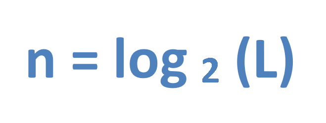
In our example, because of L = 8 then, the binary word length is n = log 2 8 = 3. For this reason, our results at the output are arranged between the minimum level of amplitude (decimal 0 or binary 000) and the maximum level (decimal 7 or binary 111).
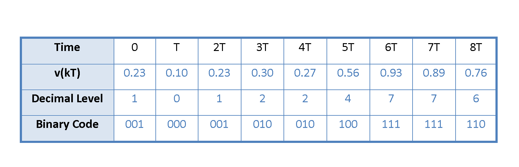
We can also collect all the input and output data in Table 1 to find out a better understanding of the conversion. The input signal contains some fractional values for each interval and the output contains some 3-bit code words for the same periods.
In Figure 2, the waveform of quantized samples (the blue graph) can be assumed as the stairstep approximation of the original analog waveform (the red one).
Binary Codes
Mostly, the code words are in the form of base-2, or binary numbers. It means they are constructed by strings of 1’s and 0’s. The symbols 0 and 1 are called binary digits or bits.
Binary codes are most familiar in representing integers. The reason for using binary numbers in digital equipment is the ease with which they can be implemented. It means the electronic components and circuits must be capable of assuming two discrete states to represent 0 and 1.
A typical digital code word would be like this array:
b7 b6 b5 b4 b3 b2 b1 b0 = 1 0 1 1 1 0 0 1
It is composed of eight bits. The subscripts correspond to the position of a particular bit in the sequence. The ‘1’ at the extreme left (b7 in the example) is called the ‘most significant bit’ or MSB, and the ‘1’ at the right (b0 in the example) is called the ‘least significant bit’ or LSB.
The straight or natural binary is the simplest way of representing quantities with binary numbers. In this case, the subscripts correspond to a power of 2 associated with the weight of each bit in the string. In the natural binary strings, the values related to serial bits are in a sequence of this form:
[2n-1 ,2n−2 ,2n-3, … ,22 ,21 ,20]
It means the position of a bit in the sequence defines its weight. Then, in a natural binary integer code having n bits, the LSB has the minimum weight of 20 (= 1) and the next bit has a weight of 21 (= 2), and so on up to the MSB, which has the maximum weight of 2n–1.
The decimal (base 10) value of a binary number is obtained by adding up the weights of all non-zero bits. When these weighted bits are added up, they form a unique number having any value from 0 to 2n -1.
Therefore, the number of bits in a binary word determines the maximum decimal value that can be represented by that word. This maximum value is determined with Equation 2:
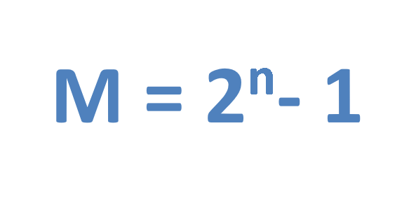
where M is the maximum decimal value and n is the number of bits in the word.
Thus, the largest decimal number that can be represented by our previous example is 23 – 1 = 7.
Digital Waveforms
Unlike an analog signal which varies continuously, a digital signal has defined discrete levels or states. The signal switches or changes suddenly from one state to the other. Digital signals with two discrete levels of voltage are also referred to as binary signals.
In Pulse Code Modulation, the binary data are represented by a sequence of bits. In a simple representation, a binary waveform can be made up of a series of pulses. When the level of the waveform is HIGH, a binary 1 is present and when the waveform is LOW, a binary 0 is present.
The symbol ‘1’ is usually represented by a positive voltage between 1 and 12 volts and the symbol ‘0’ is mostly represented by a zero voltage or some values close to it (for example +0.1 volt). In this manner, a conducting transistor may represent a ‘1’, whereas a cut-off transistor may represent a ‘0’.
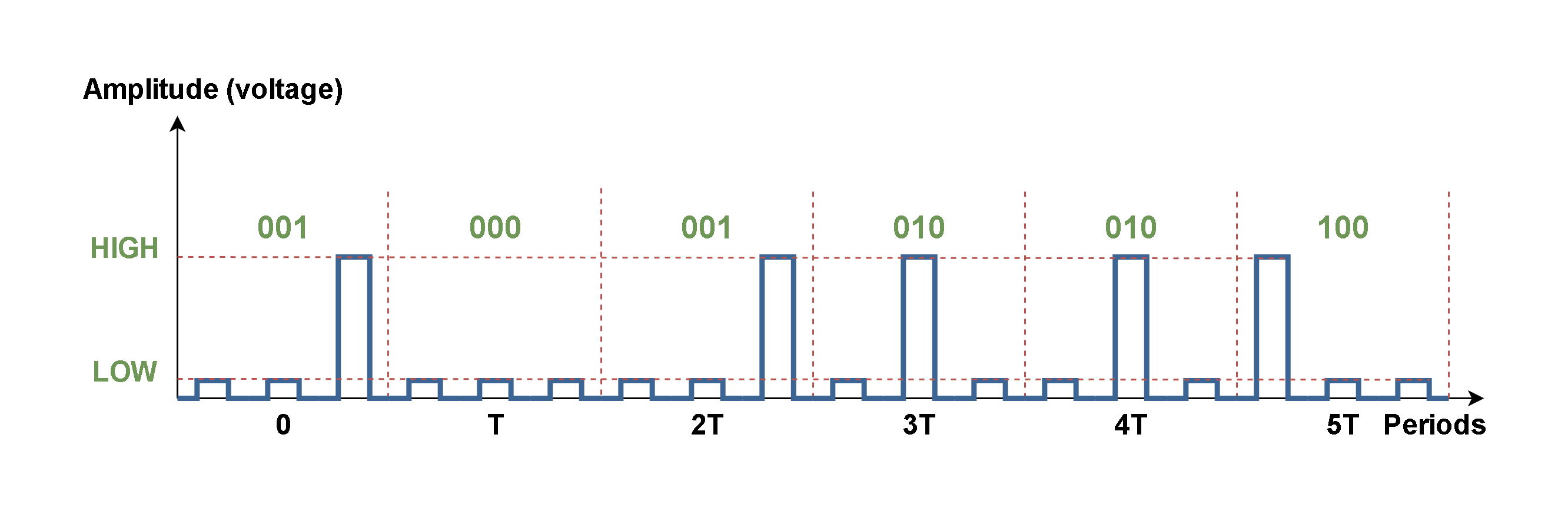
Figure 3 shows the results of Table 1 as a digital waveform of outputted binary codes. In this figure, just the results of 6 periods (from 0 to 5T) are plotted.
The Length Of Binary Words
Let’s consider an analog signal at the input of A/D converter. Here we can digitize the signal in three ways, as shown in Figure 4.
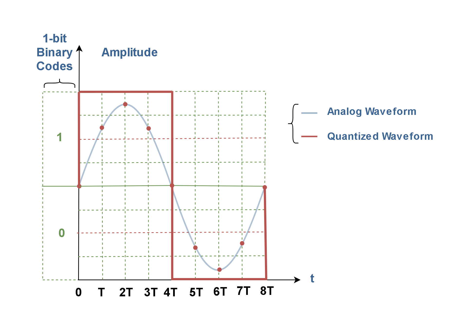
In the first case, we choose the step size so large that the output has only two states and we express the values with only one bit, i.e., just zero or one value! What is obvious is that in this case (n=1 and L=2) the accuracy is very low and this type of processing does not give us any correct information about the signal status.
As Figure 5 shows, the similarity between the analog signal (the blue curve) with the quantized signal (the red square wave shape) is very low and most of the details are missing because of coarse approximation. This case is completely inefficient and may not have any practical advantages.
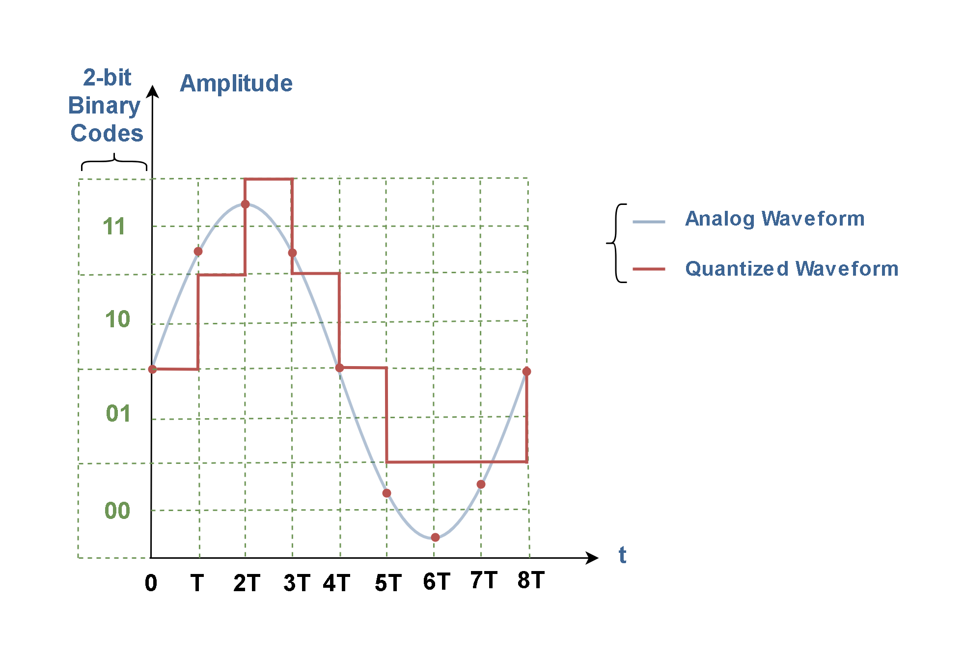
In the second case, we set parameters n=2 and L=4. It is clear that in this case, if we reduce the size of the steps and make the divisions smaller, we can have 4 numerical values in the output and express the values with 2 bits (from value 00 to 11).
As Figure 6 shows the similarity between the analog signal with the quantized signal is still low and some of the details are missing. This case is also impractical.
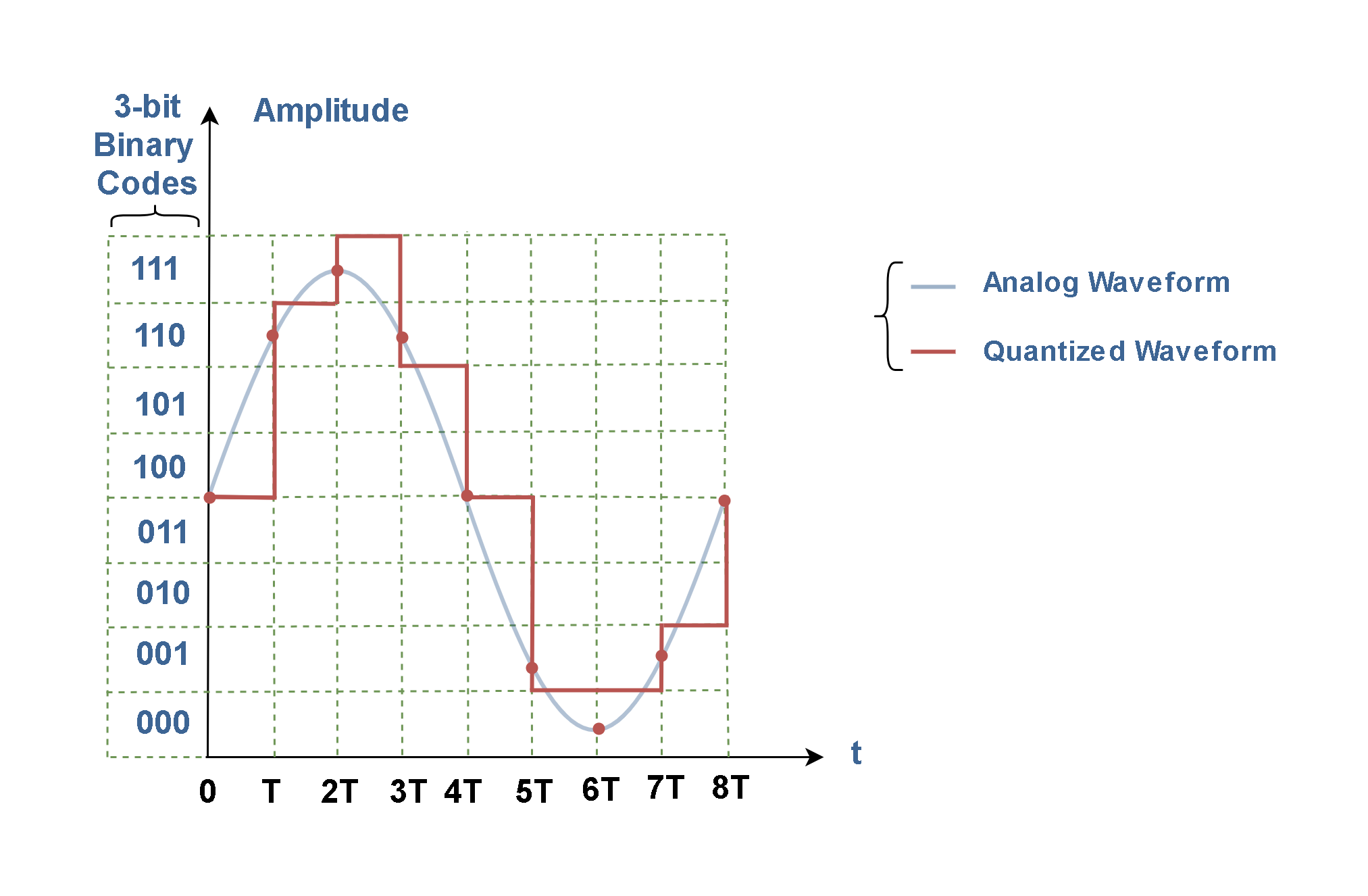
In the third case, the divisions are made smaller again and we reach 8 states in the output in which we can express the values with 3 binary bits (from 000 to 111). Here, because we have used more output bits, the accuracy has slightly increased and there is less error. As Figure 7 shows the similarity between the analog waveform and the digital signal has been corrected slightly.
It is obvious if the quantization step size (q) is smaller, the quantization error will be smaller too. In other words, for better accuracy and fewer errors, we need to increase the number of bits in the configuration of A/D conversion systems.
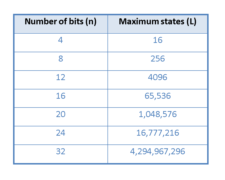
Essentially, most of the digital systems work with a fixed-length binary word. Word lengths of 4, 8, 12, 16, 20, 24, and 32 bits are common in digital systems.
Table 2 describes the most usable number of bits in different applications and the maximum number of available states which they offer for quantization.
Here are some examples:
- A common binary word length in microcomputers, data storage, processing, and transmission equipment is 8 bits.
- Consumer digital video applications also use 8-bit words.
- Digital commercial audio applications use 16-bit words.
- Compact discs (CDs) also use 16 bits to store digital information.
- A single high-quality PCM audio channel usually requires 20-bit word lengths.
Conclusion
Theoretically, the analog-to-digital conversion will never be 100% accurate, and a finite amount of information will be lost forever during the quantization and round-off process. Naturally, the presence of this ‘approximation’ causes some error in the output. It means when the digital representation is converted back to analog, the result will not be identical to the original waveform.
In practical terms, by decreasing the quantization step size, it is possible to reduce the error to such small values that it may be ignored in many applications. The sequence length (n) can be chosen to suit the specific needs of the application.
Summary
- A/D converters represent sequences of bits.
- Binary means two—two states or two discrete levels.
- Because the base of the binary number system is 2, only two symbols (0 and 1) are used to represent any quantity.
- The best-known code (other than base 10) is natural or straight binary (base 2).
- Digital equipment processes binary words.
- Digital waveforms consist of voltage levels that are changing back and forth between the HIGH and LOW levels or states.
- The A/D operation is never completely free of the error caused by approximation which is the natural effect of quantization.
- The more the number of quantization divisions and the smaller the distance between the numbers, the better the approximation will be.


