Digital to Analogue Converter (R-2R)
The R-2R Digital-to-Analogue Converter is a type of data converter that transforms a digital binary number into an analog output signal that is proportionate to the value of the digital number using two precision resistors. The binary-weighted digital-to-analog converter, in contrast to the R-2R DAC, produces an analog output voltage that is the weighted sum of the separate inputs.
The R-2R Digital-to-Analogue Converter is a type of data converter that transforms a digital binary number into an analog output signal that is proportionate to the value of the digital number using two precision resistors.
The binary-weighted digital-to-analog converter, in contrast to the R-2R DAC, produces an analog output voltage that is the weighted sum of the separate inputs. Because of this, the ladder network of this design necessitates a wide variety of precision resistors, rendering it both costly and unfeasible for most DACs that require lower resolution levels.
Given that the binary-weighted DAC is built upon a summing amplifier topology-based closed-loop inverting operational amplifier, this kind of data converter design would be suitable for a D/A converter with a few bits of resolution. However, building an R-2R digital-to-analog converter with an R-2R resistive ladder network is a far easier method that only needs two precise resistances.
There are just two resistive values used in the R-2R resistive ladder network. No matter how many bits are used to create the ladder network, the first resistor has the base value “R,” and the second resistor has twice the value of the first resistor, or “2R.”
For instance, because the base resistor “R” is not particularly important, we may just use a conventional 1kΩ resistor for it, and a 2kΩ resistor for “2R” (or multiples of it). As a result, 2R’s resistive value will always be twice that of the base resistor, R. In other words, 2R = 2*R. This indicates that, in comparison to the prior weighted resistor DAC, it is considerably simpler for us to maintain the necessary precision of the resistors along the ladder network. However, what exactly is an “R-2R resistive ladder network”?
R-2R Resistive Ladder Network
The “ladder” descriptor derives, as its name suggests, from the resistors employed in the network being arranged in a ladder-like fashion. A straightforward method of transforming digital voltage signals into an equivalent analog output is to use an R-2R resistive ladder network.
The ladder network receives input voltages at different places along its length; the more input points, the higher the R-2R ladder’s resolution. The output signal obtained from all these input voltage points is obtained from the ladder’s end and utilized to power an operational amplifier’s inverting input.
The output voltage of an R-2R resistive ladder network, thus, is solely dependent on the interaction between the input voltages. It is essentially just lengthy strings of parallel and series-linked resistors functioning as interconnected voltage dividers along their length. Examine the following simple 4-bit R-2R ladder network (4-bits due to its four input locations).
4-bit R-2R Resistive Ladder Network
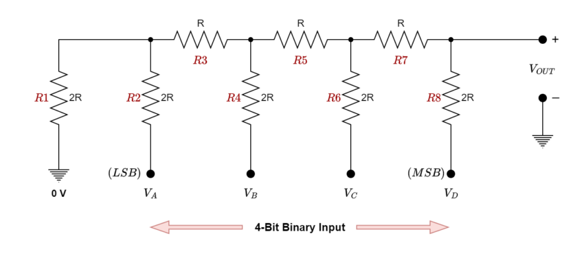
Although this 4-bit resistive ladder circuit may appear complex, it just involves connecting resistors in series and parallel configurations and applying basic circuit rules to determine the output’s proportionate value by working backward to the input source. Assume that all the binary inputs VA=VB=VC=VD=0V i.e., grounded. Therefore, 0000 is the binary code that corresponds to these four inputs.
By starting from the left side and applying the concise formula for two parallel and series resistors, we can get the ladder network’s equivalent resistance as follows:
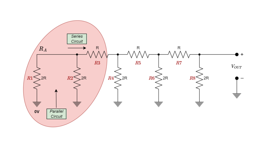
Resistors R1 and R2 are in “parallel” with each other but in “series” with resistor R3. The equivalent resistance of these three resistors may then be found; for ease of use, we’ll refer to it as RA.
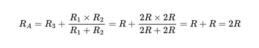
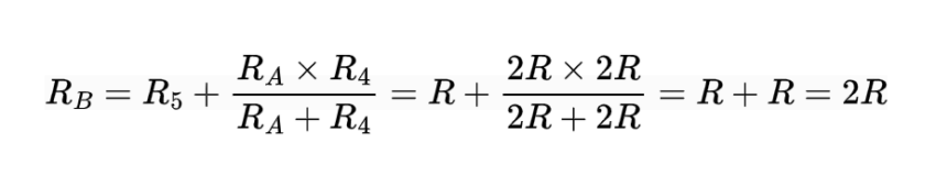
In such case, “2R =RA are equal. It is now clear that the equivalent resistance, denoted as “RA,” is parallel to R4 and in series with R5.
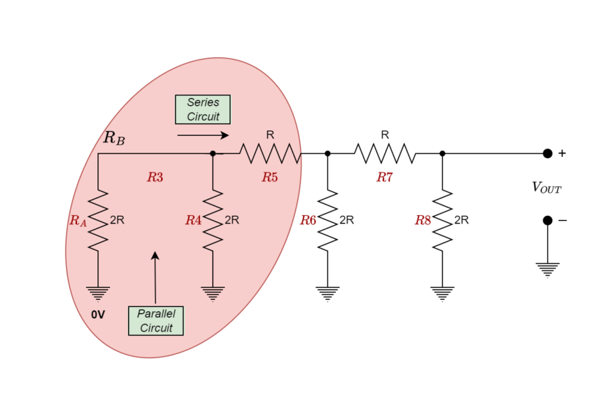
Once more, we may determine this combination’s equivalent resistance and refer to it as RB.
So, the equivalent resistance RC will be;
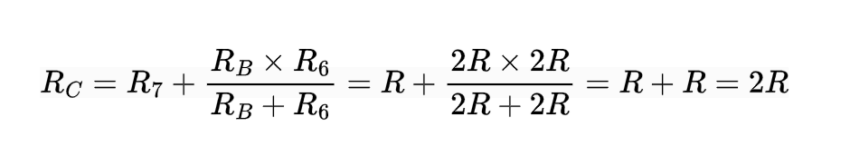
Once more, the resistor combination RC is equal to “2R,” which, as shown, is in parallel with R8.
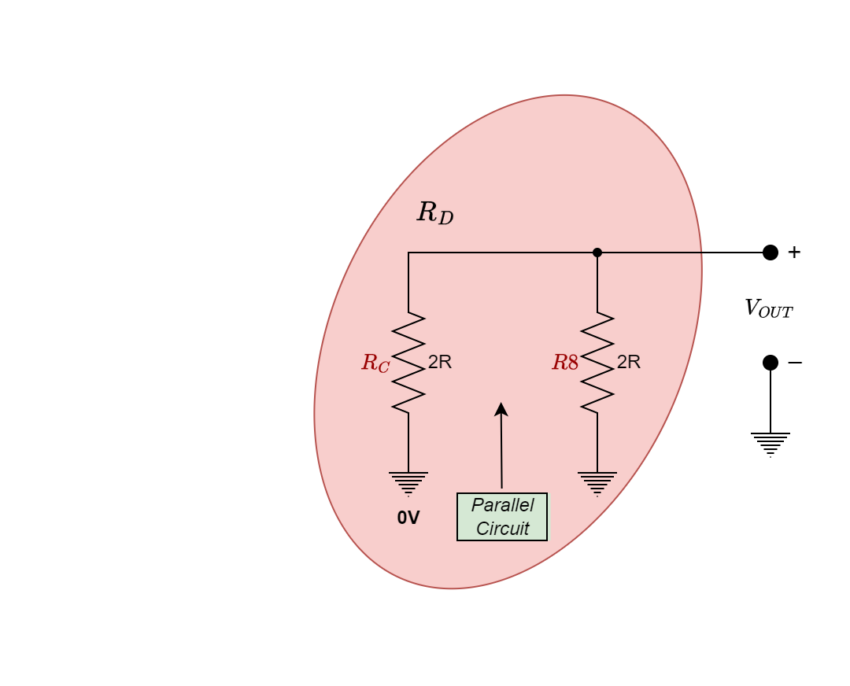
As we’ve already seen, the outcome of two parallel resistors with identical values is ½, thus 2R in parallel with 2R equals an equivalent resistance of R. Therefore, when a binary code of “0000” is applied to its four inputs, the entire 4-bit R-2R resistive ladder network, which is made up of individual resistors coupled together in parallel and series combinations, has an equivalent resistance (REq) of “R.”
Consequently, our fundamental 4-bit R-2R digital-to-analog converter circuit would resemble this when applied with a binary code of “0000” as an input:
R-2R DAC Circuit with Four Zero (LOW) Inputs
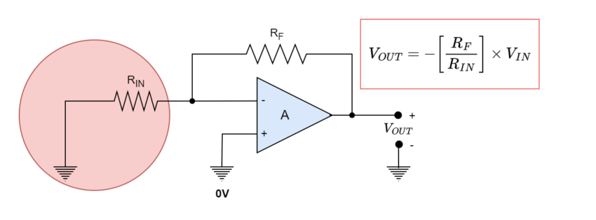
The formula for an inverting operational amplifier’s output voltage VOUT is given as (RF/RIN)*VIN. With RIN connected to ground (0V), there is no voltage value for input (VIN = 0), thus if we set RF equal to RIN (RF = RIN = 1), the output voltage would be (1/1)*0 = 0 volts. Thus, an analog output of 0 volts is produced by a 4-bit digital input of 0000 for a 4-bit R-2R DAC with four grounded inputs (LOW). As a result, the output voltage will be “zero” volts.
Now we will see, connecting input bit VA HIGH to +5 volts, how the output voltage of the op-amp is comparable to the resistive value of the R-2R ladder network.
R-2R DAC with Input VA
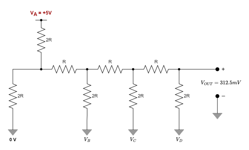
As shown in the figure, VA input is HIGH and grounded at logic level “1,” whereas all other inputs are grounded at logic level “0.” Since the R-2R ladder network is a linear circuit, we can determine Thevenin’s equivalent resistance using the same parallel and series resistance computations as previously to determine the expected output voltage. Consequently, 312.5 milli-volts (312.5 mV) is determined as the output voltage or VOUT.
With a 4-bit R-2R resistive ladder network, this 312.5 mV voltage shift is categorized as the Least Significant Bit (LSB) as it is one-sixteenth the value of the +5V input voltage (5/0.3125 = 16). As the least important bit, input VA will therefore establish the “resolution” of our straightforward 4-bit digital-to-analog converter as the smallest voltage shift in the analog output is equivalent to a single-step change in the digital inputs. Therefore, 312.5mV (1/16th) for a +5V input will be the value for our 4-bit DAC.
As we connect the input bit VB HIGH to +5 volts, let’s examine what happens to the output voltage.
R-2R DAC with Input VB
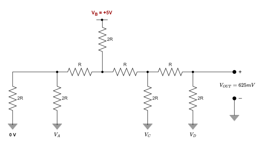
The output voltage, VOUT, is determined to be 625mV, or one-eighth (1/8th) of the value of the +5V input voltage (5/0.625 = 8) with input VB HIGH and logic level “1” and all other inputs grounded at logic level “0.” Additionally, we observe that the output voltage doubles when only the input bit VA is applied. This is to be expected because the input bit is the second bit and has twice the weighting of the first bit.
Let’s now examine the effects of connecting input bit VC HIGH to +5 volts on the output voltage.
R-2R DAC with Input VC
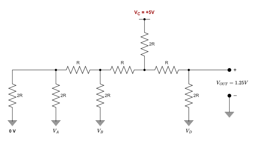
One-quarter (1/4) of the value of the +5V input voltage (5/1.25 = 4) is the output voltage or 1.25 volts when input VC is HIGH, logic level “1” is used, while the remaining input bits are at logic level “0.” Once more, we can observe that this voltage is four times the value of bit VA and double the output of input bit VB. This is because the weighting of input VC, which is the third bit, is double that of the second bit and four times that of the first bit.
Lastly, let’s see what happens to the output voltage when input VD is HIGH, i.e., connected to +5 volts.
R-2R DAC with Input VD
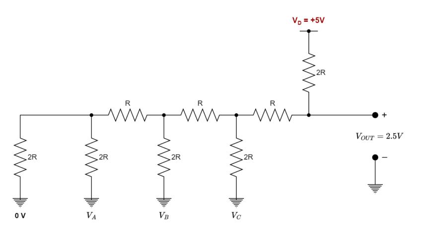
The output voltage, VOUT, is determined to be 2.5 volts when input VD is HIGH, logic level “1” is used, and all other inputs are at logic level “0.” This is one-half (1/2) of the +5V input voltage (5/2.5 = 2). Once more, we can see that because this voltage is the fourth bit and is therefore categorized as the Most Significant Bit (MSB), it is twice the output of input bit VC, four times the value of bit VB, and eight times the value of input bit VA.
Then, we can observe that, given that input VA controls the DAC’s resolution because it represents the LSB, input VB is double to VA, input VC is four times greater than VA, and input VD is eight times greater than VA, we can use the following equation to determine the relationship between the analog output voltage of our 4-bit digital-to-analog converter.
Digital-to-Analogue Output Voltage Equation
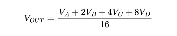
Where the 16 (24) potential combinations of inputs to the 4-bit R-2R ladder network of the DAC are represented by the denominator number of 16.
Since each input bit’s weighting is always based on the least significant bit (LSB), we may extend this equation further to get a generalized R-2R DAC equation for any number of digital inputs for an R-2R D/A converter. This gives us a generalized equation of:
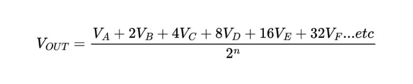
Where “n” is the number of digital inputs in the DAC’s R-2R resistive ladder network, which results in the resolution VLSB = VIN/2n.
Thus, it is evident that input bit VA when HIGH will result in the least amount of output voltage change, while input bit VD when HIGH will result in the most amount of output voltage change. Therefore, the predicted output voltage is determined by adding together the effects of each HIGH-connected input bit.
Since each input will have a step increase equal to the LSB, the ladder network should ideally result in a linear relationship between the input voltages and the analog output. To this end, we can create a table of expected output voltage values for all 16 possible combinations of the four inputs, with +5V denoting a logic “1” condition as demonstrated.
4-bit R-2R D/A Converter Voltage Output
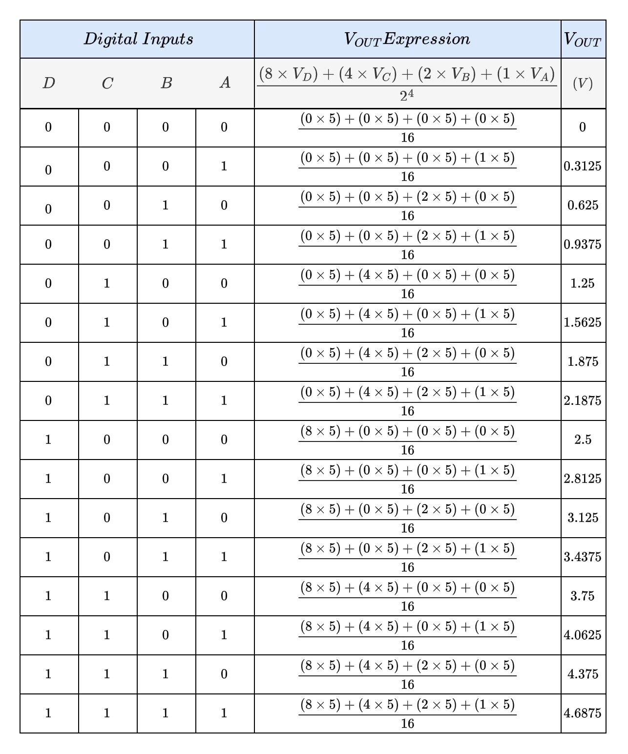
The full-scale analog output voltage for a binary code of 1111, as you may have noted, is always smaller by the equivalent of one LSB bit (312.5mV in our case), and it never reaches the same value as the digital input voltage (+5V).
On the other hand, the analog output voltage approaches full-scale when all input bits are HIGH. Similarly, when all the input bits are LOW, VOUT approaches 0 volts.
R-2R Digital-to-Analogue Converter
Since we know the characteristics and operations of the R-2R resistive ladder network, we can use it to create an R-2R digital-to-analog converter. We can construct a straightforward R-2R digital-to-analog converter like the following by utilizing our 4-bit R-2R resistive ladder network and attaching it to an inverting operational amplifier circuit:
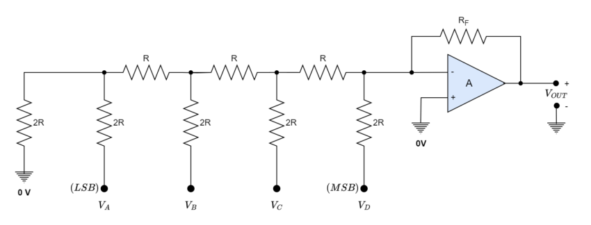
A combinational or sequential logic circuit, a data register, a counter, or even just switches can be utilized to create the digital logic circuit that powers the D/A converter. The application will determine how an R-2R D/A converter of “n” bits should be connected. Digital-to-analog converters are included in all-in-one boards like the Arduino and Raspberry Pi, which makes programming and interface considerably simpler. Numerous well-known DACs are available, including the 8-bit DAC0808.
R-2R D/A Converter Example:
A 4-bit R-2R digital-to-analog converter is built to use the output from a digital logic circuit to regulate the speed of a small DC motor. Analyze the analog output voltage from the DAC when the input code is the hexadecimal number “B” if the logic circuit utilizes 10-volt CMOS devices.
- The number eleven in decimal notation is equivalent to the hexadecimal character “B.” The binary code “1011” in binary is equivalent to the decimal number eleven. That is, 10112 = B16. Thus, bit D = 1, bit C = 0, bit B = 1, and bit A = 1 are the input bits for our 4-bit binary integer, 10112.
Assuming the feedback resistor (RF) to be equal to “R,” the circuit for our R-2R D/A converter will be as follows:
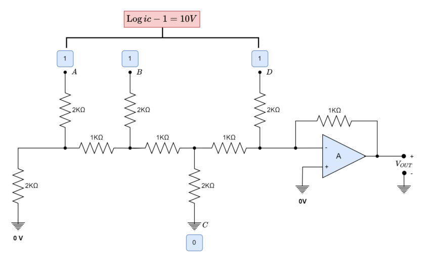
The R-2R network will receive an input voltage of 10 volts since the digital logic circuit employs 10-volt CMOS chips. Since this 4-bit ladder DAC also has 24 possible input permutations, the output voltage for a binary code of 10112 is determined using the equation above:
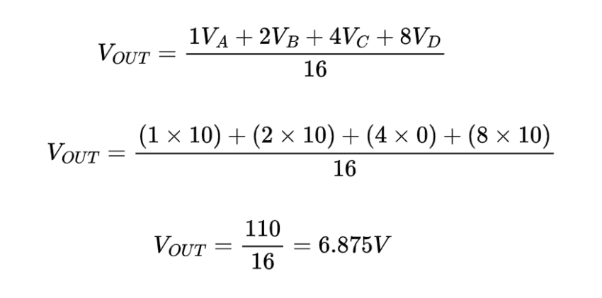
Hence, when the input code is 10112, the analog output voltage that is utilized to regulate the DC motor is computed as follows: -6.875 volts. Keep in mind that the operational amplifier’s inverted input is the reason the output voltage is negative.
- The least significant bit (LSB), which is specified as follows, will have a resolution of equal to:
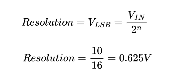
In this 4-bit R-2R digital-to-analog converter example, the smallest step change in the analog output voltage, or VOUT, is 0.625 volts for a 1-bit LSB change in the digital input. That is, rather than changing in a straight linear fashion, the output voltage varies in stages or increments of 0.625 volts.
4-bit Binary Counting R-2R DAC
By now, perhaps, we should be able to construct an R-2R ladder DAC using just two resistor values: one is the base value “R,” and the other is twice that amount, or “2R.” With four input data lines, A, B, C, and D, we have created a 4-bit R-2R DAC in our straightforward example above. This gives us sixteen (24) distinct input possibilities, ranging from “0000” to “1111”.
There are several methods to create the binary code for these four digital input lines, including solid-state switches, microcontrollers, and digital circuits. Nevertheless, using a 4-bit binary counter like the 74LS93 is an intriguing alternative.
With the application of a single external clock signal, the 4-bit J-K ripple counter 74LS93 may be made to count from 00002 to 11112 (MOD-16) and reset back to zero (0000). Asynchronous and sometimes referred to as a “ripple” counter, the 74LS93 generates a 4-bit binary output because of internal J-K bistables responding to a clock or timing input.
The counters’ output lines divide the external clock’s frequency (or period) by a factor of 2, 4, 8, and 16 as the clock pulse ripples through the four J-K flip-flops to produce the necessary 4-bit output count sequence, which runs from 00002 to 11112.
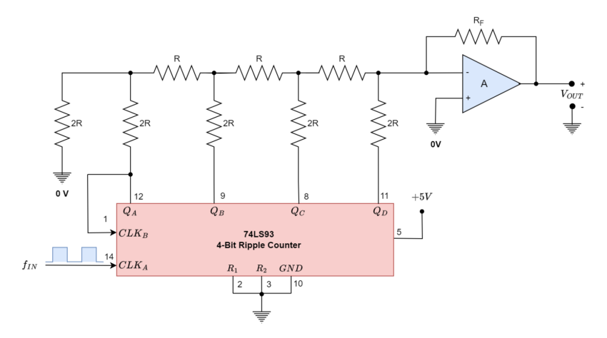
Observe that the external CLKB input needs to be linked to the QA (pin-12) output to count upward from 0000 to 1111, and that input CLKA (pin-14) needs to receive the input timing pulses.
This straightforward 4-bit asynchronous up counter uses the same counting sequence seen in the top table, which is based on the 74LS93 binary ripple counter. A clock pulse applied to the QA, QB, QC, and QD outputs causes a one-step change.
The operational amplifier’s input recognizes this step shift and, to the binary code at the R-2R ladder inputs, produces a negative voltage (inverting op-amp). Every step’s output voltage value will line up with the values shown in the above table.
The maximum negative output voltage of the digital-to-analog converter will be produced by the ripple counter counting in succession with the four outputs providing an output sequence of binary values up to the 15th clock pulse, at which point the outputs are set to 11112 (decimal 15).
The op-amp’s output is reset to zero volts on the sixteenth pulse, which also resets the counter’s output sequence and counts back to 0000. When the subsequent clock pulse is applied, a fresh counting cycle from zero to VOUT(max) is initiated.
The following time diagram displays the output sequence for this straightforward 4-bit binary asynchronous counting R-2R D/A converter.
4-bit R-2R DAC Timing Diagram
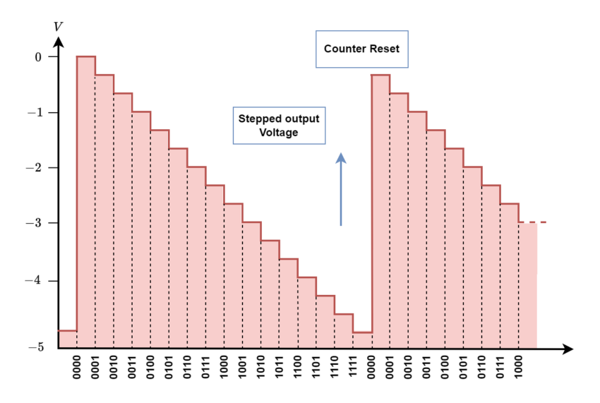
Therefore, it is evident that when the ripple counter counts from 00002 to 11112, respectively, the operational amplifier’s output voltage swings from zero volts to its maximum negative value. This straightforward circuit might be used to continuously change the speed of a DC motor from slow to fast and back again at a rate defined by the clock period, or it could be used to adjust the brightness of a light connected to the output of the op-amp.
This time, the R-2R DAC and ripple counter are set up for 4-bit operation. However, by utilizing widely accessible binary ripple counters, like the CMOS-4024 7-bit (÷128), CMOS-4040 12-bit (÷4096), or the larger CMOS-4060 14-bit (÷16,384) counter, and by including additional input resistors in the R-2R ladder network, like those offered by Bourne’s, the resolution (LSB) of the circuit can be significantly reduced, resulting in a smoother output signal from the R-2R digital-to-analog converter.
Conclusion
- An R-2R Digital-to-Analogue Converter uses two precision resistors to transform a digital binary number into an analog output signal that is proportionate to the value of the digital number.
- The mentioned generalized equation may be used to determine the output voltage of an R-2R digital-to-analog converter with any number of digital inputs; VO= (VA+2VB+4VC+8VD+16VE+32+VF…)/2n
- The full-scale analog output voltage with a binary code of 1111 never reaches the same value as the digital input voltage and is always smaller by the equivalent of one LSB bit. Similarly, when all the input bits are LOW, the resulting lower resolution of LSB causes VOUT to approach 0 volts.
- To make an R-2R digital-to-analog converter, an op-amp coupled with a 4-bit R-2R ladder network can be utilized. The output of a digital logic circuit is used to control a tiny DC motor’s speed.
- Using a 4-bit binary counter with an op-amp, like the 74LS93 ripple counter, is an interesting alternative. It causes the operational amplifier’s output voltage to swing from zero volts to its maximum negative value when the ripple counter counts from 00002 to 11112, respectively.
- The speed of a DC motor may be continually adjusted using 4-bit binary counter circuits, going from slow to fast and back again at a pace determined by the clock period. It may also be used to control the brightness of a light that is connected to the op-amp’s output.


