Display Decoder
Display Decoder A Display Decoder is a type of Binary Decoder, discussed in the previous article, with the main purpose to drive a display. As such, it is a combinational logic circuit that converts input binary data into a corresponding number of output lines which are connected to a display for displaying information such as decimal or hexadecimal numbers.
Display Decoder
A Display Decoder is a type of Binary Decoder, discussed in the previous article, with the main purpose to drive a display. As such, it is a combinational logic circuit that converts input binary data into a corresponding number of output lines which are connected to a display for displaying information such as decimal or hexadecimal numbers.
The Binary or Digital Decoder converts one form of binary data into another defined by its logical functions and is commercially available in the form of an IC package. The most commonly known Digital Decoder is a Binary Coded Decimal (BCD) to 7-Segment Display Decoder which is used to display decimal & hexadecimal numbers from the BCD number. The 7-segment display, as the name says, is divided into seven (7) segments and each segment is made of a Light Emitting Diode (LED) which can be independently turned ON or OFF. The combination of lit segments makes up a decimal number from “0” to “9” or a hexadecimal number from “A” to “F”. For example, commercially available TTL Package 74LS47 is BCD to 7-segment Decoder IC.
7-Segment Display
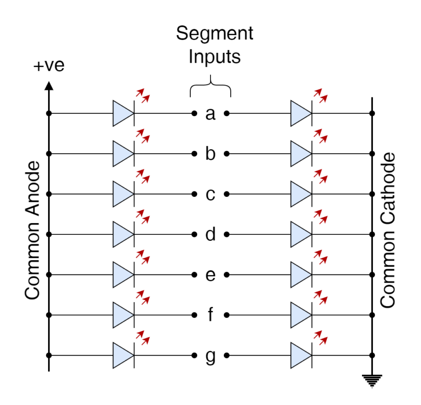
The common LED has two terminals i.e. Anode & Cathode and, as such, each segment (LED) of a 7-segment display has two terminals. In order to reduce wires one of the terminals is kept common and the rest of the wires are used to control the specific segment. This makes a total of eight (8) input connections amongst which seven (7) are for controlling & one (1) is a common line connected to the either positive or negative terminal of the power source. In most of the 7-segment displays, additional input is present to display Decimal Point (DP). Depending on the common terminal, a 7-segment display can be classified into the following categories:
Common Anode Display
In this type of 7-segment display, the anodes of all seven (7) segments are connected together and are connected to logic “HIGH” or positive power terminal. Each segment is then illuminated by connecting its Cathode terminal to logic “LOW” or ground.
Common Cathode Display
In this type of 7-segment display, the cathodes of all seven (7) segments are connected together and are connected to logic “LOW” or ground terminal. Each segment is then illuminated by connecting its Anode terminal to logic “LOW” or ground.
The above-mentioned configurations either common anode or cathode can be used to display decimal and hexadecimal values on a 7-segment display.
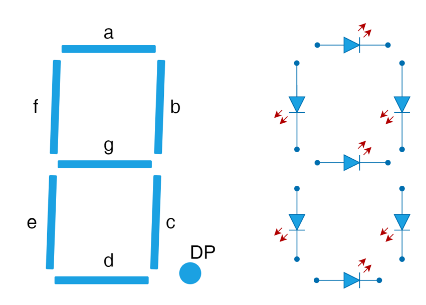
Format of 7-Segment Display
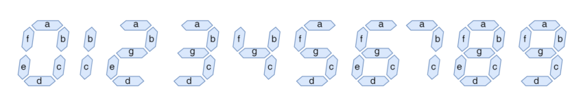
In the following figure, the format of a 7-segment display is showing placement of each segment. The segments are designated as “a”, “b”, “c”, “d”, “e”, “f”, and “g”. In order to display the digit “1” on it, segments “b” & “c” will be illuminated only. Similarly, for displaying digit “7”, segments “a”, “b”, & “c” will be illuminated, accordingly. The same pattern will be followed to display other numeric and alphabetic values and a truth table can be produced illustrating the combination of illuminated segments required for displaying alphanumeric values.
7-Segment Truth Table
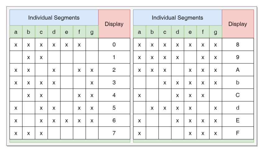
It is eminent from the above Truth Table that a total of eight (8) input connections are required for displaying binary values into 0 to 9 or alphabets from A to F. As each segment consists of a LED which typically takes around 20mA of current when illuminated. So, displaying digit “1” requires illumination of two segments i.e. “b” & “c”, and the total amperage of (2X20mA) is 120mA. Under the illumination of all segments for displaying digit “8” a total amperage of (2X20mA) 140mA is required. Utilization of a number of Inputs/ Outputs (IO) and supplying excessive amperage from a low-cost/ low-powered microcontroller is not feasible. The reduction in number of IOs can be reduced by driving display through a BCD to a 7-segment decoder and displaying on more than one display can be established by multiplexing technique in the microcontroller.
Binary Coded Decimal (BCD)
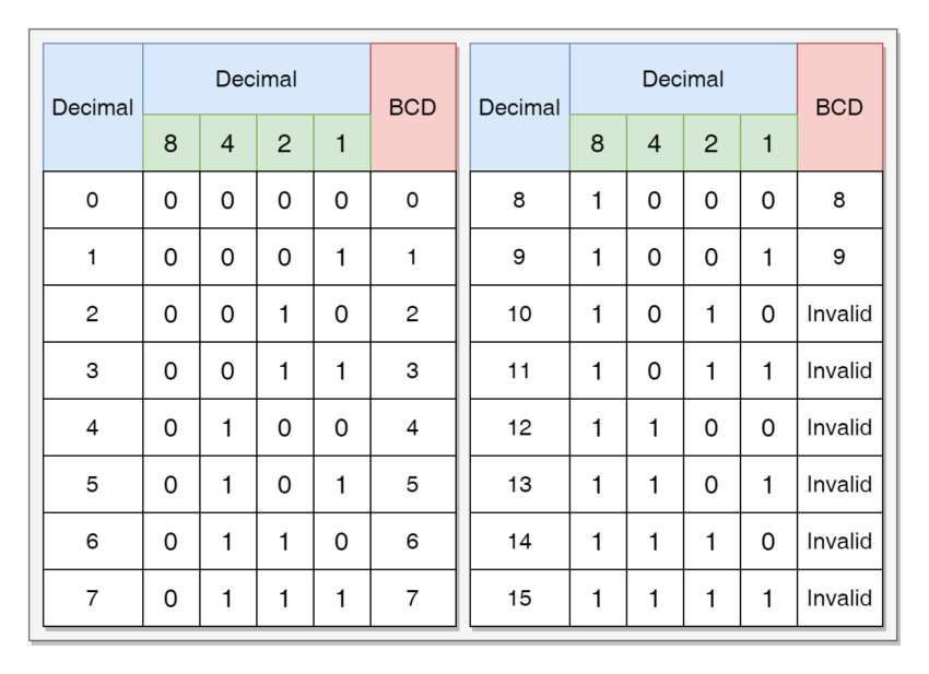
The Binary Coded Decimal or BCD is a 4-bit binary code to represent a numeric digit. The BCD is also termed as the “8421” code where 8, 4, 2, or 1 corresponds to 2 raised to the power of 3, 2, 1, or 0, respectively. The 4-bit or nibble (half-byte) is used to code a decimal value from 0 to 9 or hexadecimal from 0 to F. However, BCD represents only decimal values from 0 to 9, and the rest of the values from A to F are not used which resultantly produces invalid input for these A to F inputs. The Binary pattern for these BCD numbers is shown in the following truth table.
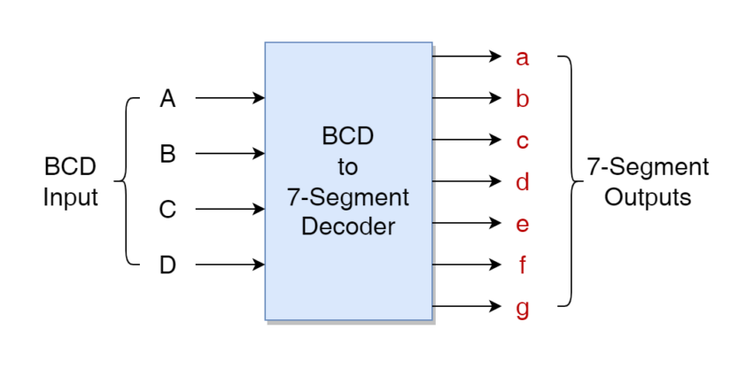
BCD to 7-Segment Display Decoders
As discussed earlier, a Display Decoder is preferred for displaying numbers on a 7-segment display when using a microcontroller due to its limited number of input and output lines as well as less power handling capability. The commercially available BCD to 7-segment Decoders such as TTL 74LS47 or 74LS48 is used for this purpose and has four (4) binary inputs & seven (7) output lines to drive each corresponding 7-segment. These decoders can run a 7-segment display displaying values from 0 to 9 and, similarly, another similar setup can be used to display numbers from 00 to 99 using an eight-bit (8-bit) or a byte of binary data and is termed as packed BCD (8-bit).
Commercially Available Display Decoders
LED Type
- Common Anode: TTL 74LS47
- Common Cathode: TTL74LS48
LCD Type
- CMOS CD4543
LED or 7-segment displays require a current limiting resistor in each segment and its value is dependent on the LED type. LCD-type displays use less power compared to their counterpart LED displays and are preferred.
Examples of Display Decoder
A number of BCD to 7-segment Decoder examples are given below to illustrate its operation.
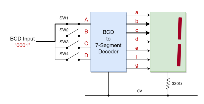
Example No. 1
In the following example, the number 1 (one) is displayed on the 7-segment. The corresponding BCD number for one (1) is “0001” as given in the above table. The BCD to 7-segment Decoder decodes this BCD to illuminate corresponding segments by setting logic “HIGH” or “LOW”, depending on the Common Cathode Anode configuration of 7-segment, on its “b”, & “c” output lines.
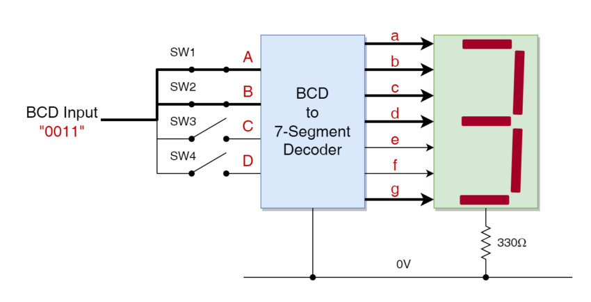
Example No. 2
In the following example, the number 3 (three) is displayed on the 7-segment. The corresponding BCD number for three (3) is “0011” as given in the above table. The BCD to 7-segment Decoder decodes this BCD to illuminate corresponding segments by setting logic “HIGH” or “LOW”, depending on the Common Cathode Anode configuration of 7-segment, on its “a”, “b”, “c”, “d”, & “g” output lines.
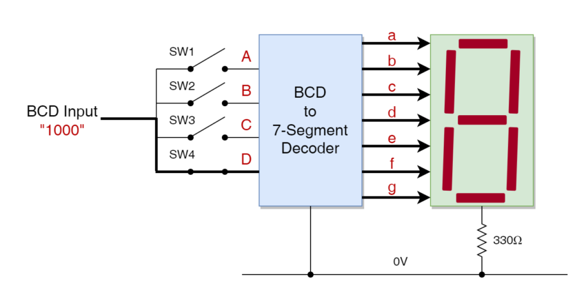
Example No. 3
In the following example, the number 8 (eight) is displayed on the 7-segment. The corresponding BCD number for eight (3) is “1000” as given in the above table. The BCD to 7-segment Decoder decodes this BCD to illuminate corresponding segments by setting logic “HIGH” or “LOW”, depending on the Common Cathode Anode configuration of 7-segment, on its “a”, “b”, “c”, “d”, ‘e”, “f” & “g” output lines.
Conclusion
- A Digital Decoder is a combinational logic circuit that converts n-bit binary code into a number of output lines.
- A Display Decoder is a digital decoder used for driving displays for representing binary or binary-coded information.
- A 7-segment display comprises seven (7) Light Emitting Diodes (LED) which are enlightened in a combination to display numeric values ad these segments are termed “a”, “b”, “c”, “d”, “e”, “f”, & “g”.
- The 7-segment display comes in either a common anode or a common cathode configuration wherein the anodes or cathodes of each segment are joined together, respectively.
- The 7-segment display has a total of eight (8) input lines and requires 140mA of current for its seven (7) LED segments. The increased number of input lines and significant amperage makes it impractical to be used with a microcontroller having limited I/O lines and reduced power handling capacity.
- A Binary Coded Decimal (BCD) is a 4-bit (nibble) code used for displaying denary numbers from 0 to 9 only. A BCD to 7-segment Decoder is used with a microcontroller to drive a 7-segment display.
- Commercially available BCD to 7-segment Decoders are TTL 74LS47 or 74LS48 IC Packages.


