Logic AND Function
Logic AND Function The output of Logic AND Function is true only when all of its inputs are in true logic states otherwise the output of Logic AND Function will be false (in case any of the inputs is false). All of the logic functions follow Boolean Algebra and relevant theorems.
Logic AND Function
The output of Logic AND Function is true only when all of its inputs are in true logic states otherwise the output of Logic AND Function will be false (in case any of the inputs is false).
All of the logic functions follow Boolean Algebra and relevant theorems. The Boolean Algebra is similar to that of Normal Algebra in that it follows similar laws and theorems except the Boolean Algebra involves a set of values either “TRUE” or “FALSE” but not both at the same time. In normal algebra, 1 + 1 = 2 but in Boolean algebra 1 + 1 = 1 as there are only two values [True (1) and False (0)] in the short set, and one of them only occurs at a time, not both. In other words, in Boolean Algebra A + A = A, not 2A as compared to normal algebra.
The Boolean Algebra was developed by George Boole in 1854 and authored “The Laws of Thought” which contains Boolean Algebra based on a simplified version of the Group or Set.
The logic functions or gates are based on Boolean Algebra and describe logic functions in simple switching actions performed by logic gates. The basic logic gates include AND, OR, and NOT logic gate functions.
The logic AND function require two or more inputs and expects a similar state (TRUE) of inputs at the same time in order to output a TRUE logic. At any instant, any of the inputs in a FALSE state leads the AND logic to output a FALSE state. In the following figure, a symbol along with the algebraic function of logic AND gate is shown.

In terms of Electrical Circuit, the logic AND functions are represented by switches connected in “Series”. In Boolean Algebra, the logic AND function is the product of inputs (variables) and is denoted by a dot (.) between the inputs which may not be necessary i.e. A.B or AB both represents a AND logic on inputs A & B. The occurrence of a state of operation of a switch is independent of the order in which they take place. It means that the logic AND function follows the Commutative Law i.e. A & B = B & A. According to Commutative Law, the output is independent of the position of a variable or input.
Presentation of AND Function using Switches
In the following figure, an electrical circuit comprising of two switches (A & B), a battery, and a lamp is shown. The electrical circuit is equivalent to a logic AND function where switches A & B represents logic AND functions inputs.
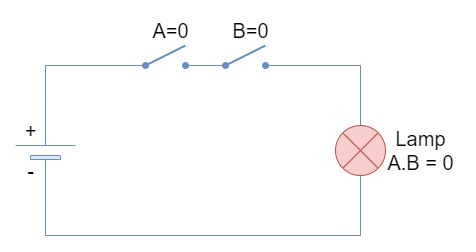
The logical states of “0” & “1” represent a switch with “Open” & “Closed” positions, respectively.
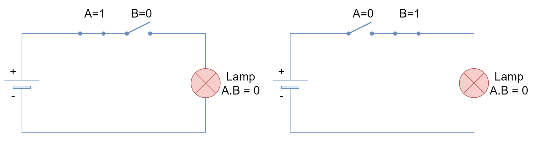
When both inputs are FALSE or “0” then both switches are open and the lamp remains at FALSE state as well. Likewise, when any of both inputs, irrespective of order or placement, is FALSE then the lamp still remains at FALSE state as shown in the following figure.
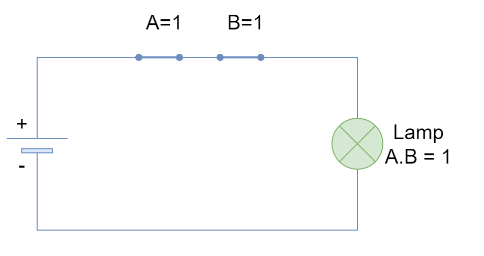
However, when both of the inputs are TRUE or “1” then the lamp turns to TRUE or ON state. The series combination of switches truly depicts the logic AND function where both switches (inputs) require to be TRUE to give a TRUE output.
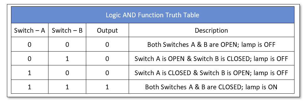
Logic AND Truth Table
The above case of series switches is represented in the following truth table.
Boolean Algebra Laws
A brief overview of Boolean Algebra Laws relevant to logic AND is given below in form of figures. A more detailed overview of these laws is provided in another article on Boolean Algebra.
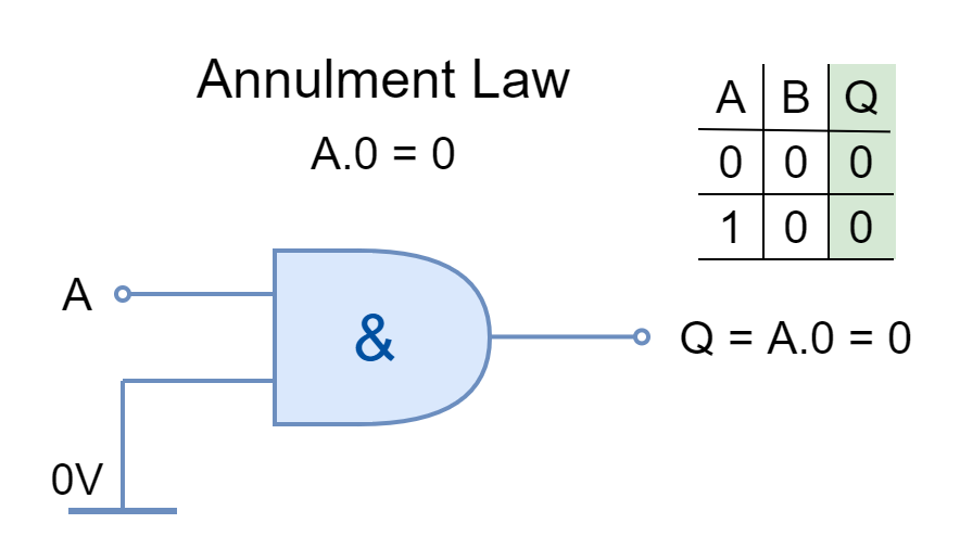
Annulment Law
The input AND’ed by ‘0’ or OR’ed by ‘1’ is stated as Annulment Law. It nullifies or diminishes the effect of the other input
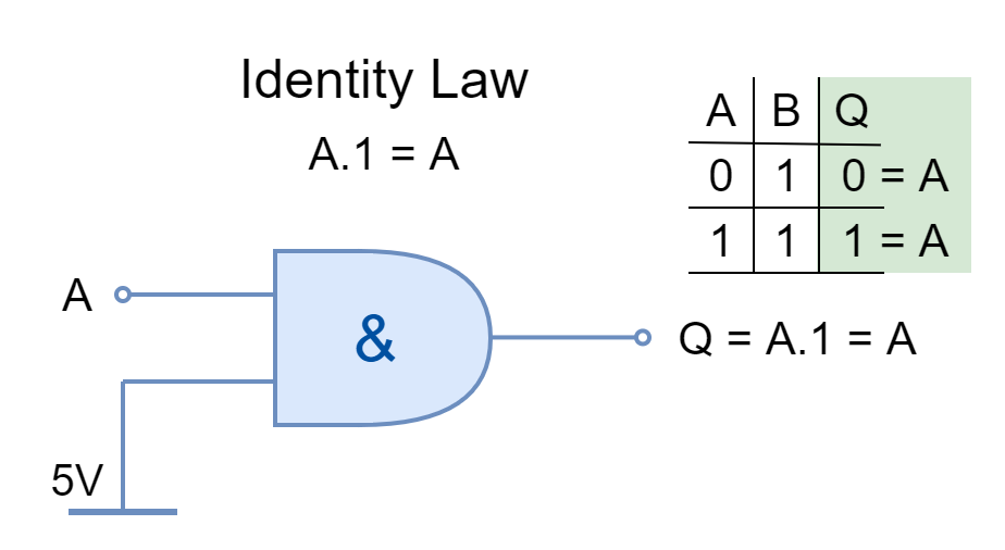
Identity Law
The input AND’ed by ‘1’ or OR’ed by ‘0’ is stated by Identity Law. It keeps the identity of the input.
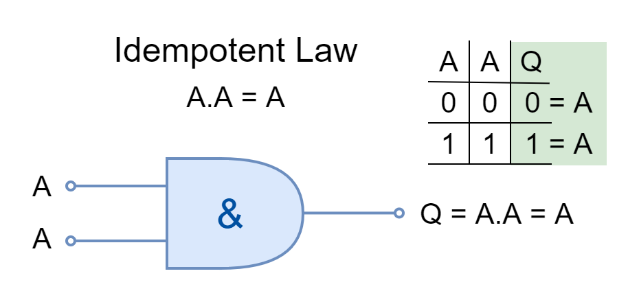
Idempotent Law
The same inputs AND’ed or OR’ed together are stated under Idempotent Law. The logical operation can be applied multiple times without changing the result.
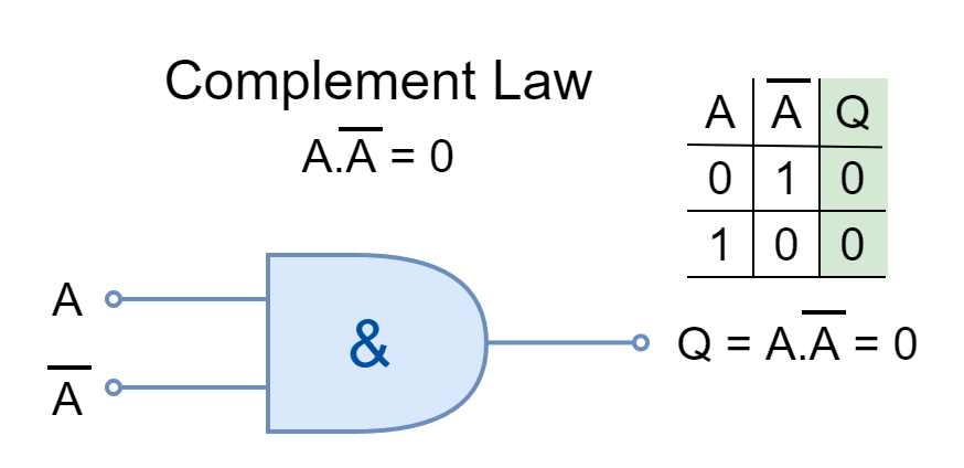
Complement Law
In Boolean Algebra, the complement is the opposite of a logical input such as ‘0’ is the complement of ‘1’ and vice versa. The input and its complement AND’ed or OR’ed together is described by Complement Law.
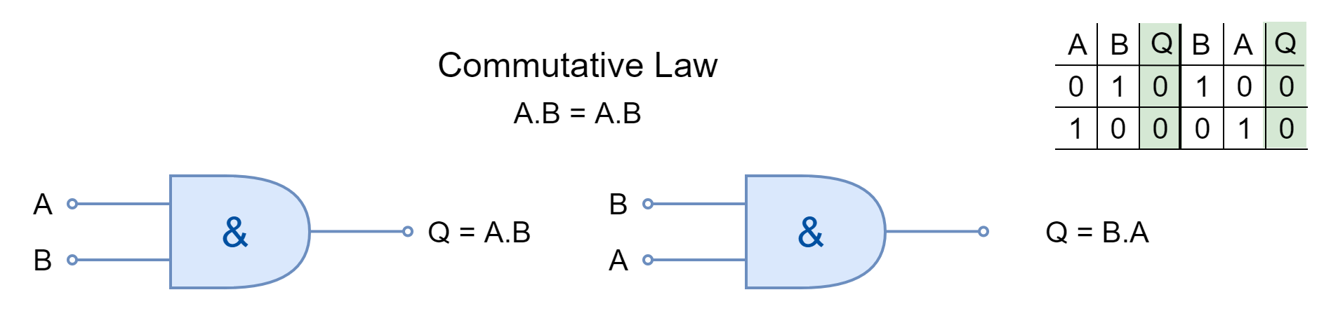
Commutative Law
The commutative law states that changing the order of operands (variables or inputs) does not change the result. In Boolean Algebra, the inputs can be interchanged without changing the results under commutative law.
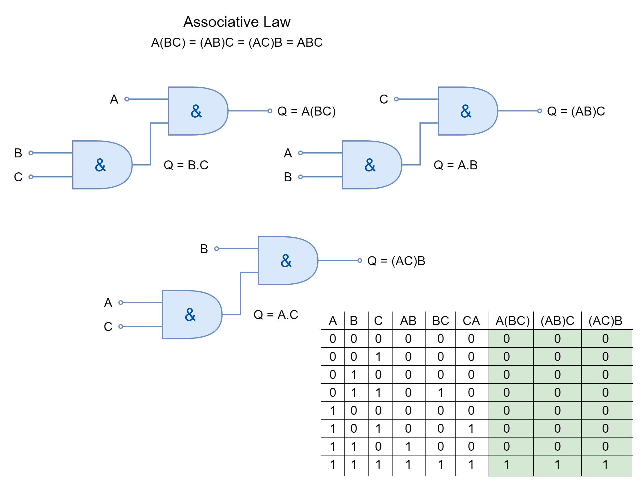
Associative Law
The associative law of multiplication states that the operands grouped differently in multiplication produce the same result. The inputs AND’ed together can be placed interchangeably to form different groups under the Associative Law.
Commercially Available Logic AND Gates
The logic AND gates are available in form of I.C. packages which contain multiple AND gates with multiple inputs to each gate. The selection depends merely on the application and the number of logic are required. They come in both Transistor-Transistor Logic (TTL) and Complementary Metal Oxide Semiconductor (CMOS) family packages. A few commercially available logic AND gates are given below:
- TTL 74LS08 2-input Quadruple AND Gates
- TTL 74LS11 3-input Triple AND Gates
- TTL 74LS21 4-input Double AND Gates
- CMOS 4081 2-input Quadruple AND Gates
Conclusion
- The logic AND function give output TRUE only when all of its inputs are in a TRUE state.
- Any of the inputs in the FALSE state will lead the AND function to the FALSE output.
- The logic AND function can be represented by an electrical circuit having two switches in series. When both of the switches are closed (inputs at TRUE states) then supply passes to the load/ lamp.
- The logic AND gates can be cascaded together to obtain logic AND having more than two inputs.
- The commercially available packages come in different I.C. packages. Each IC package contains multiple AND gates.


