Switching Theory
Switching Theory The switching theory uses switches in order to understand the operation and functioning of digital logic gates and circuits. The switching theory helps in developing better theoretical knowledge and concepts of digital logic circuits involving logical inputs producing a specific relational logical output.
Switching Theory
The switching theory uses switches in order to understand the operation and functioning of digital logic gates and circuits. The switching theory helps in developing better theoretical knowledge and concepts of digital logic circuits involving logical inputs producing a specific relational logical output. As it has already been discussed that Boolean data type has only two distinctive states i.e. “0” or “1”. They are also referred to as “LOW” and “HIGH” or “OFF” and “ON”, respectively. Digital logic input and output can have only these two states. A switch or an electromechanical contact of a relay also has only two distinctive states i.e. “OFF” or “ON”. Therefore, a digital logic input or output can be represented by a physical switch, and Boolean Algebra laws, rules, and theorems can be applied to them. The Boolean expressions can be expressed by switching theory which eases the understanding of digital logic gates.
The understanding of digital logic gates is essential when dealing with complex logic circuits or microprocessors. The digital logic gates are the basic building blocks of combinational and sequential logic circuits. The combinational logic circuits are dependent on only external inputs or signals applied to them. Whereas, the sequential logic circuits are dependent on the present state, its output, and externally applied inputs.
Theory of a Switch
A switch can be thought of as a wall switch which is normally found in households to turn “ON” or “OFF” a light/ lamp. A switch can also be an electromechanical contact of a relay to allow the flow of current in either direction.
A Normally-open Switch
In the following circuit, a voltage source is connected to a lamp through a normally-open switch. Under normal conditions i.e. the switch is open, the electric path between the voltage source and the lamp is not established and no current flows. The lamp does not glow or illuminate. However, when the switch is pressed i.e. switch closed, the electric path between the voltage source and the lamp gets established. A current flows to the lamp from the voltage source through the switch and illuminates the lamp.
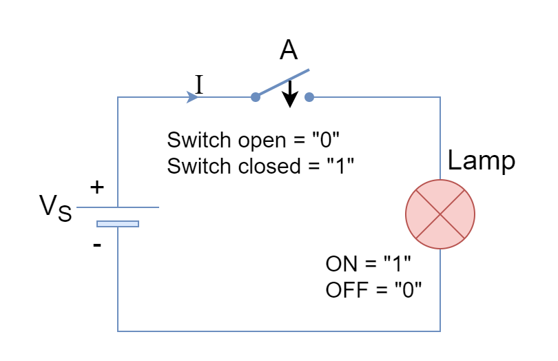
The switch positions i.e. “OFF/ OPEN” and “ON/ CLOSED” are equivalent to Boolean states of “0” and “1”, respectively. Likewise, lamp states of “OFF” and “ON” by “0” and “1”, respectively. The switch can be represented by an input (A) and lamp as an output (L).
When the switch/ input (A) is open “0” then the lamp/ output (L) is also “0” or not illuminated. Likewise, when the switch/ input (A) is closed “1” then the lamp/ output is “1” or illuminated. This can be illustrated by the equivalent switching truth table which is shown below.
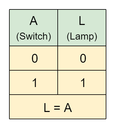
From the above table, the switch equals lamp i.e. A = L which means that when the switch is “OFF” the lamp will also be “OFF” and this phenomenon holds under the “ON” state of the switch. The switch used in the above circuit is normally-open and it has to physically make a contact to be considered closed. The other type of switch is normally closed which is opposite of normally open and has to physically break the contact in order to be considered open.
A Normally-closed Switch
In the following circuit, a voltage source is connected to a lamp through a normally-closed switch. Under normal conditions i.e. switch is closed, the electric path between voltage source and lamp is established and current flows to illuminate the lamp. However, when the switch is pressed i.e. switch open, the electric path between the voltage source and lamp breaks. The current flow along with the illumination of the lamp stops.
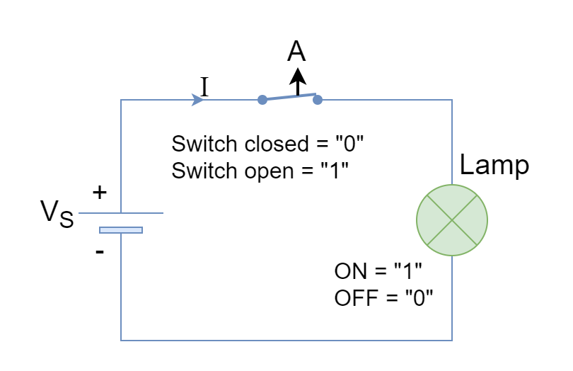
Here, the switch positions i.e. “OFF/ OPEN” and “ON/ CLOSED” are equivalent to Boolean states of “1” and “0”, respectively.
The above electric circuit can be described as when the switch/ input (A) is open “1” then lamp/ output (L) is “0” (not illuminated). Likewise, when the switch/ input (A) is closed “0” then the lamp/ output is “1” (illuminated). This can be illustrated by the equivalent switching truth table which is shown below.
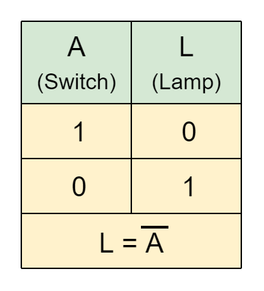
From the above table, the switch and lamp states are opposite to each other which means that when the switch is “OFF” the lamp will be “ON” and, likewise, when the switch is “ON” the lamp will be “OFF”. The normally-closed switch is performing the inversion function in terms of switching theory.
Series Switches Case
In the above circuit, a single switch is used to control the lamp operation. The single switch allowed the flow of current to the lamp in order to illuminate it. The state of a single switch is equivalent to lamp state i.e. both are “OFF” or “ON” at the same time. The addition of a switch in series with the first switch leads to a different state of affairs.
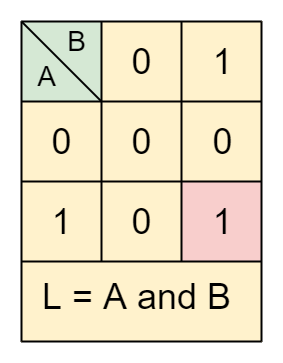
Consider the following circuit having a voltage source, a lamp, and two series switches. The switches can be labeled as inputs “A” and “B”. There open/ off states are represented by “0” and closed/ on states by “1”. The two switches make a total of four combinations to control the lamp. The first combination is A=0 & B=0, the second combination is A=0 & B=1, the third combination is A=1 & B=0, and the fourth combination is A=1 & B=1. The lamp has four states corresponding to each combination of A and B. As obvious from physical switches in series, the current will flow from the voltage source to the lamp when both switches are closed or at a logical “1” state. The series switches’ truth table is shown below:
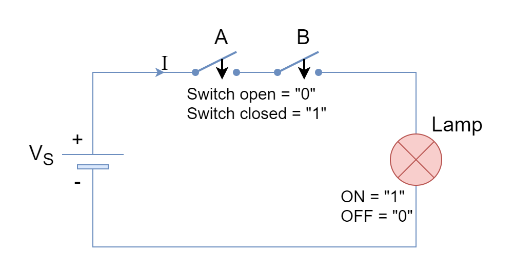
From the following truth table, it is clear that when both switches/ inputs are closed or at “1” logical state then the lamp illuminates (state of “1”). When either of the switches is at the “0” logical state, the lamp is at the “0” state. This leads to L = A and B expression. In Boolean Algebra, it is an AND logical operation which is denoted by a single dot (.) between the input variables i.e. L=A.B.
Hence, in the switching theory and operation of series switches is equivalent to a digital logic “AND” gate.
Digital Logic AND Gate
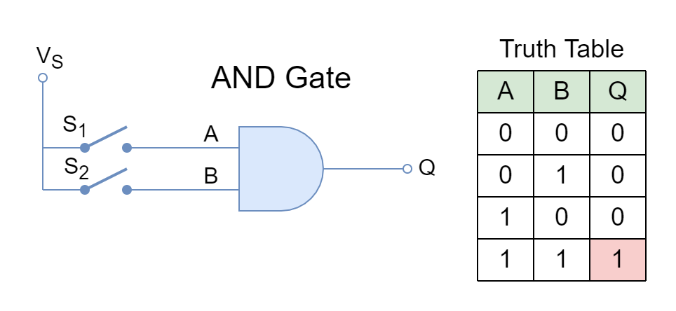
The switching theory equivalent logic AND gate is shown below along with its truth table. The switches “A” and “B” are AND’ed together to yield an output “Q”.
Parallel Switches Case
Consider the following circuit having a voltage source, a lamp, and two parallel switches. Similar to the series switches, these two parallel switches make a total of four combinations to control the lamp. The lamp has four states corresponding to each combination of A and B which are now connected in parallel to each other. As obvious from physical switches in parallel, the current will flow from the voltage source to the lamp when any of the switches is in a closed or at a logical “1” state. The parallel switches’ truth table is shown below:
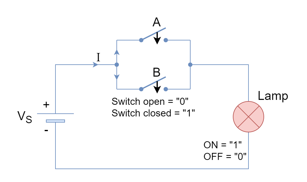
From following the truth table, it is clear that when both switches/ inputs are open or at a “0” logical state then the lamp does not illuminate (state of “0”). When either of the switches is closed or at a “1” logical state, the lamp illuminates (a “1” state). This leads to L = A or B expression. In Boolean Algebra, it is an OR logical operation that is denoted by a plus (+) between the input variables i.e. L=A+B.
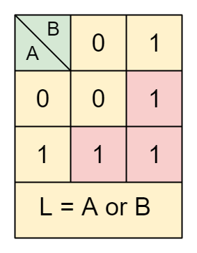
Hence, in the switching theory and operation of parallel switches is equivalent to a digital logic “OR” gate.
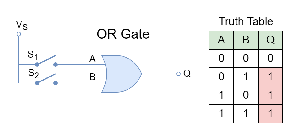
Digital Logic OR Gate
The switching theory equivalent logic OR gate is shown below along with its truth table. The switches “A” and “B” are OR’ed together to yield an output “Q”.
Idempotent Law of Switches
In the above text, the switching theory equivalent logical AND, and OR gates are discussed having two different switches or variables i.e. “A” and “B”. These two variables can be controlled by a single variable such as “A” and operation of logical AND, and OR on single variables is defined as Idempotent Law. According to Idempotent Law, the AND’ing or OR’ing of a variable with itself will yield the original variable. This means that “A” OR’ed with “A” will yield “A” and, likewise, AND operation will also yield “A”. This can simplify switching circuits as illustrated below.
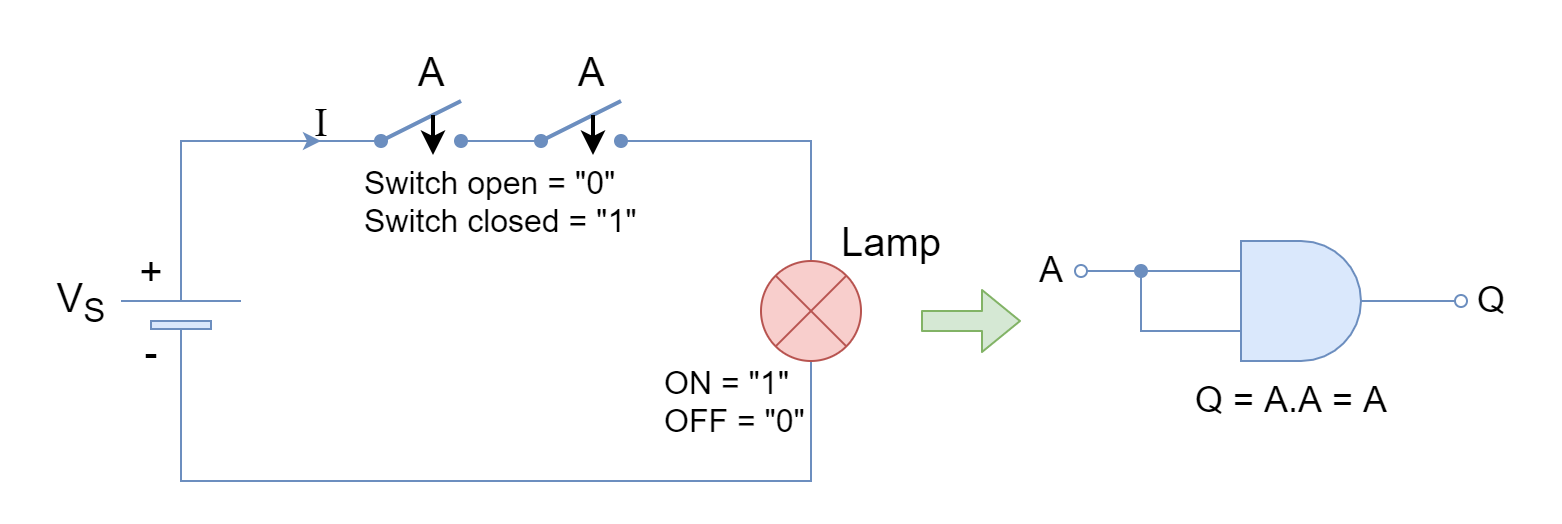
Idempotent Law of AND Function
The electric circuit constituting of same series switches along with the switching theory equivalent of AND gate is shown below.
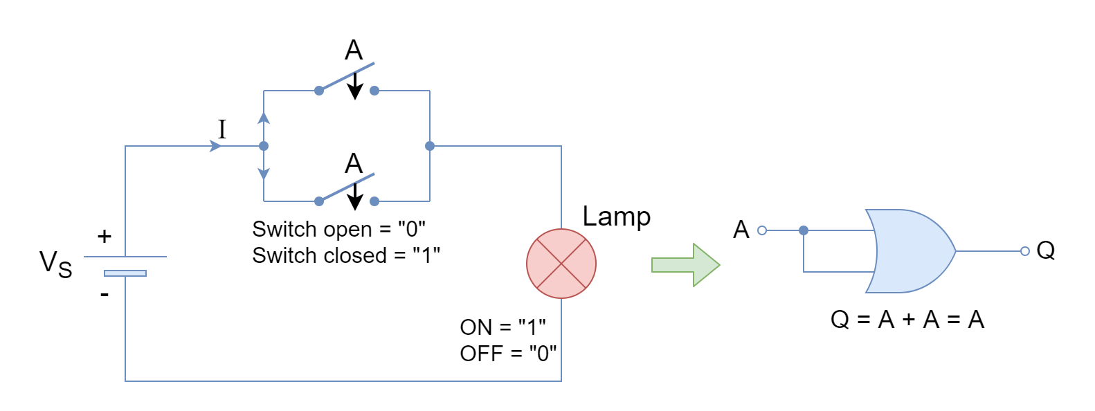
Idempotent Law of OR Function
The electric circuit constituting of same parallel switches along with the switching theory equivalent of the OR gate is shown below.
Switching theory of a Boolean Function
According to switching theory, a combination of series switches gives a logical AND (multiplication) operation which is denoted by a dot (.) between variables. Similarly, a parallel combination of series switches gives a logical OR (sum) operation which is denoted by a plus (+) between variables. Using these switching theory equivalents a Boolean function can be constructed from an electric circuit and vice versa.
Switching Theory Example
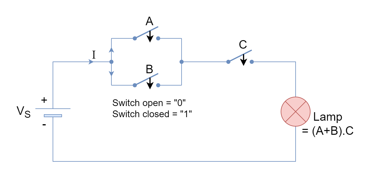
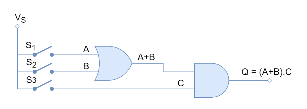
In the following figure, a Boolean function of Q = (A+B).C is implemented using switches to illuminate a lamp (Q). Likewise, a Boolean function can also be obtained from a switching circuit using switching theory.
Conclusion
- A switch can be used to express a digital state of input i.e. “OFF” equals “0” and “ON” equals “1”.
- The switching theory expresses Boolean expressions in terms of switches to help in understanding.
- The switches in series illuminate the lamp when both are “CLOSED” or “1” and constitute a logical AND operation.
- The switches in parallel illuminate the lamp when any of them is “CLOSED” or “1” and constitute a logical OR operation.
- Using switching theory, any Boolean expression can be used to construct a switching circuit and, likewise, a switching circuit’s equivalent Boolean expression can also be derived.


