Logic NOR Function
Logic NOR Function The logic NOR function gives the inverted output of the logic OR function. It complements the output of the logic OR function to give the NOT OR (NOR) function.
Logic NOR Function
The logic NOR function gives the inverted output of the logic OR function. It complements the output of the logic OR function to give the NOT OR (NOR) function. The logic NOR function is the combination of two logic functions that are OR & NOT logics. These OR & NOT logics form a series combination to produce the logic NOR function.
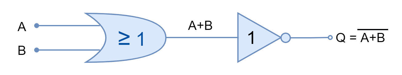
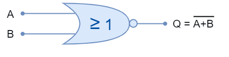
The combination of these two logics is symbolized by placing an “Inversion Bubble” at the output of an OR gate. The logic NOR symbol is shown in the following figure along with its Boolean expression. The Boolean expression of the NOR gate is represented by a sum of inputs with an overline (¯). The sum of inputs expresses OR logic and, whereas, the overline (¯) represents the NOT logic.
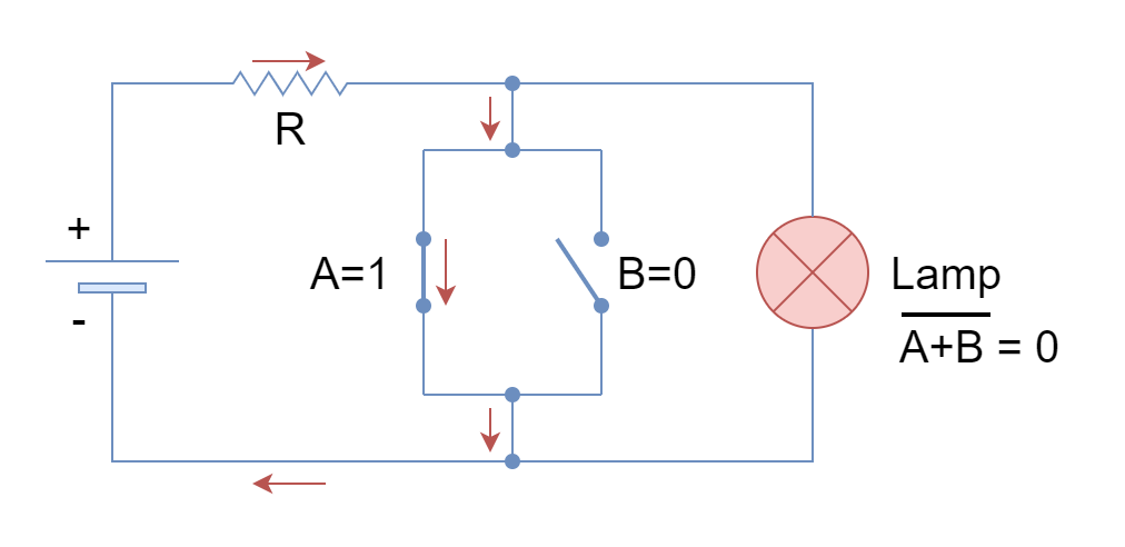
Similar to the logic OR function, the logic NOR function can be represented and explained by switches. From the previous article on Logic OR Function, it is known that OR function can be represented by parallel switches that are placed in series with the output. However, in the logic NOR function, these parallel switches (inputs) are placed parallel to the output. The representation of a logic NOR function in the form of switches is shown in the following figure.
The logical states of “0” & “1” represent a switch with “Open” & “Closed” positions, respectively.
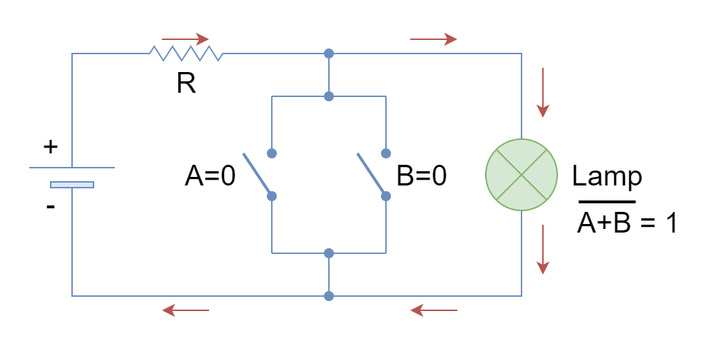
In the above figure, the current flows through the lamp to turn it ON when both switches (A & B) (inputs) are open (both at logic 0).
The closing of any of the switches changes the state of the lamp and turns OFF the lamp by providing an alternate low resistive path to a power source.
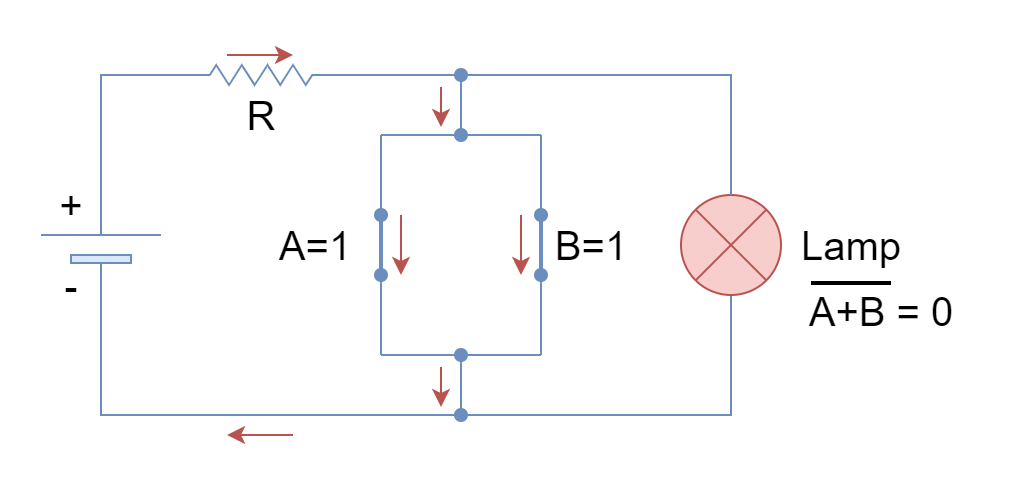
The closing of both switches (both at logic 1) does not change the state of output and the lamp remains OFF until both of the switches are opened.
The only condition for the lamp to remain ON is when all of the switches are open or at a LOW state. This is in reverse with the logic OR function which, contrarily, turns ON the lamp when any of the inputs is at a HIGH state.
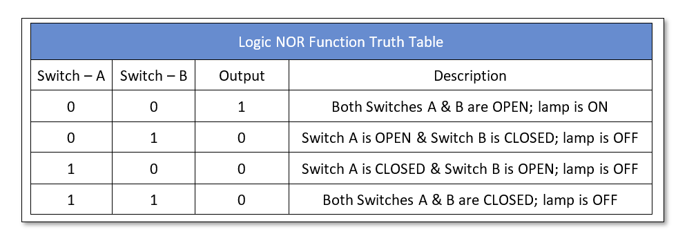
The switches representation of a logic NOR function is expressed in the form of a truth table which is given below:
Construction of NOR logic
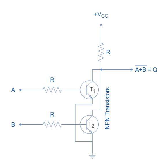
The logic NOR gate can be constructed using Resistor-Transistor Logic (RTL), Transistor-Transistor Logic (TTL), or Complementary Metal-Oxide Semiconductor (CMOS). These, basically, constitute the formation of logical families. The logic NOR gate with two inputs constructed using Resistor-Transistor Logic (RTL) is shown in the following figure.
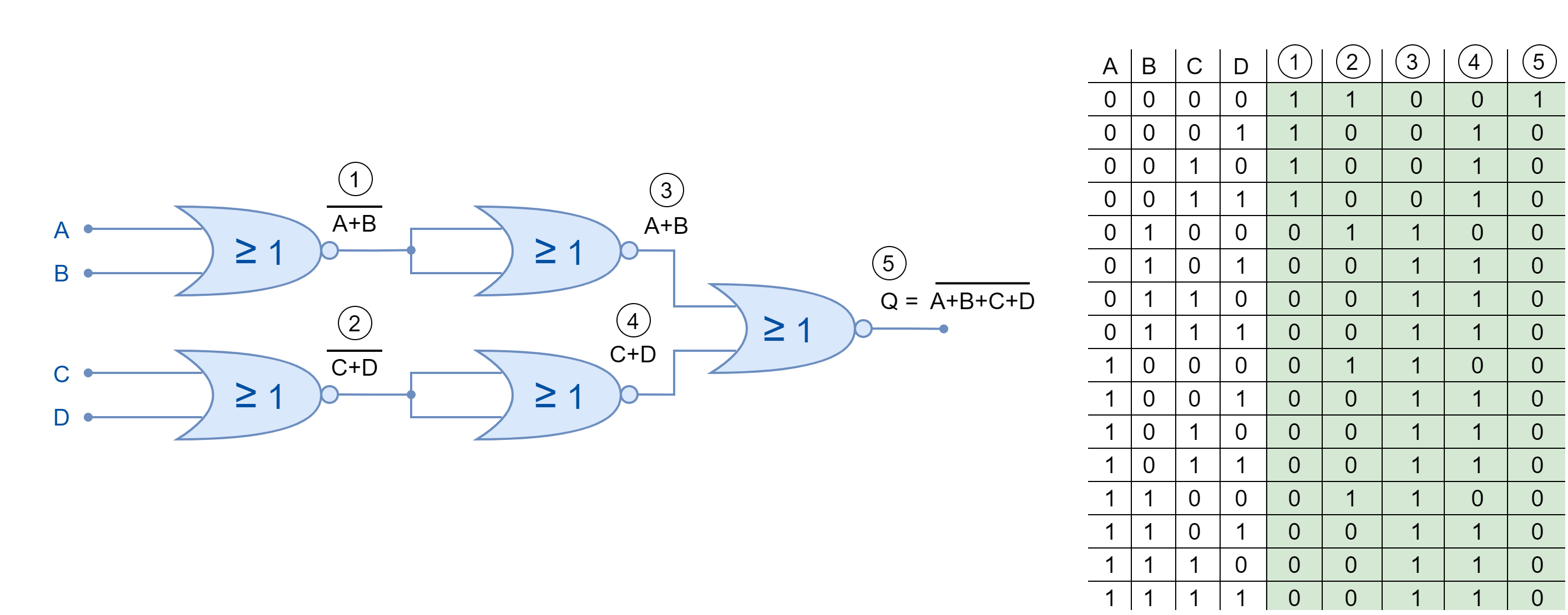
The logic NOR function can be extended to include more than two inputs. In Boolean expression form, the additional input or variable is added to the sum with an overline. In logic gates, the NOR gates are cascaded to add in more inputs as shown below.
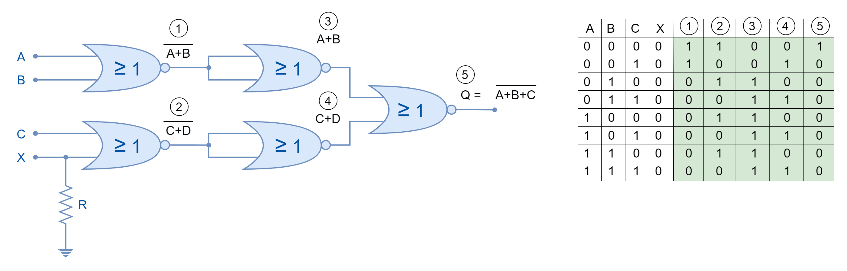
Moreover, the logic NOR function with an odd number of inputs can also be achieved by using logic “LOW” or “0” in Boolean expression form. Whereas, in the case of NOR gates, the other input (unused/ discarded) must be pulled down through a suitable resistor as shown in the following figure.
Universal Gate
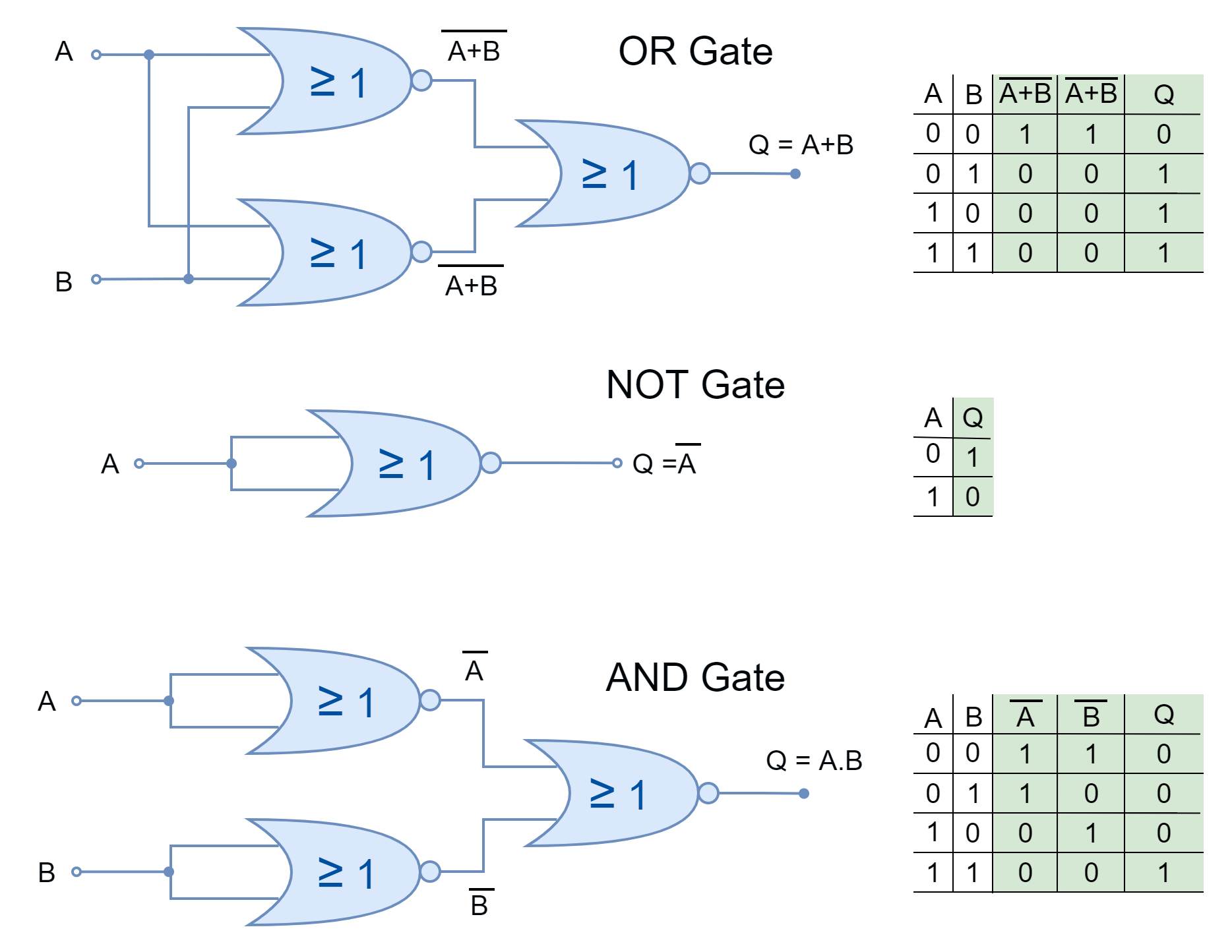
Just like the NAND gate, the logic NOR gate is also referred to as a Universal Gate as every other logic function can be constructed using it. They can construct all the functions which can be constructed using basic logic gates i.e. AND, OR, and NOT. The construction of basic logic functions using logic NOR gates is shown below.
Boolean Algebra Laws
Similar to the logic OR function, the logic NOR function follows all the Boolean algebra laws and theorems such as Annulment, Identity, Idempotent, Complement, Commutative and Associative Laws which are explained briefly in the Logic OR function.
Commercially Available Logic NOR Gates
The logic NOR gates are available in form of I.C. packages which contain multiple NOR gates with multiple inputs to each gate. The selection depends merely on the application and the number of logic gates is required. They come in both Transistor-Transistor Logic (TTL) and Complementary Metal Oxide Semiconductor (CMOS) family packages. A few commercially available logic NOR gates are given below:
- 74LS32 Quad 2-input
- CD4071 Quad 2-input
- CD4075 Triple 3-input
- CD4072 Dual 4-inputs
Conclusion
- The logic NOR function gives output TRUE only when all of its inputs are in a FALSE state.
- Any of the inputs in the TRUE state will lead the NOR function to the FALSE output.
- The logic NOR function can be represented by an electrical circuit having two parallel switches with the load. When any of the switches are closed (input at TRUE state) then supply bypasses the load/ lamp and turns it OFF.
- The logic NOR gate is also known as Universal Gate because it can construct every other logic.
- The logic NOR gates can be cascaded together to obtain logic NOR having more than two inputs.
- The commercially available packages come in different I.C. packages. Each IC package contains multiple NOR gates.