admin
-
Posts
180 -
Joined
-
Last visited
-
Days Won
5
Content Type
Profiles
Forums
Events
Everything posted by admin
-

Help for Desulfator charger lead acid battery!
admin replied to johnpham's topic in Electronic Projects Design/Ideas
Hi Johnpham, I would propose you this circuit published on Silicon Magazine (July 2009). This lead acid desulfator circuit supports 6V,12V and 24V lead acid batteries using a selection switch and it's based on popular 555 timer IC. Most of the pars are easily available and you will need to wind some air coils.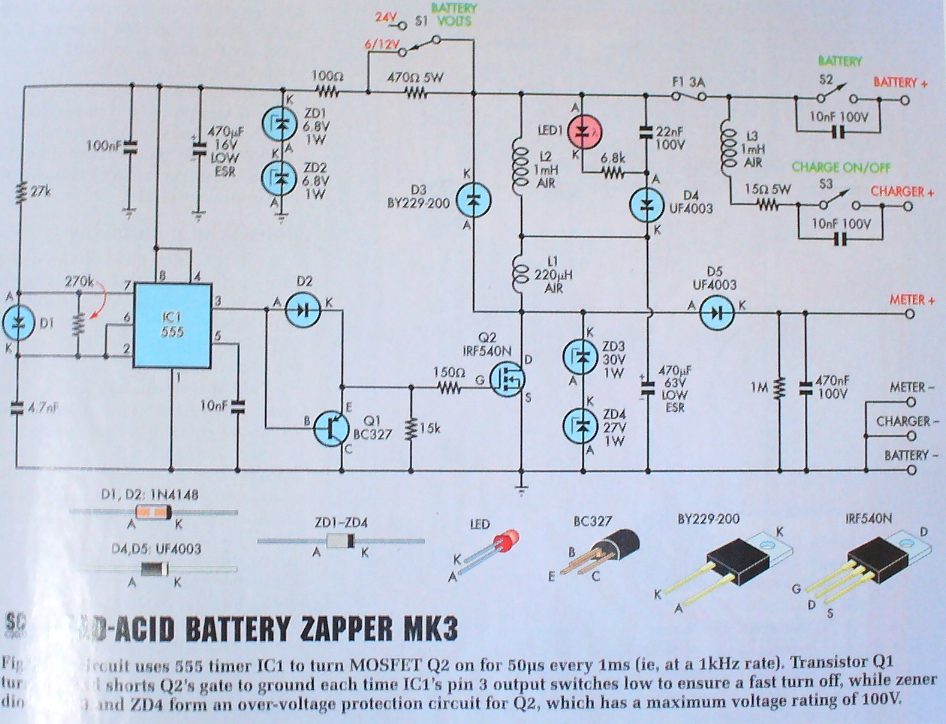
-
Hi Maleetronic, Thanks for your interest publishing a project on elab! I personally handle the project submissions and manually adding them to our repository after reviewing. So if you would like to submit your project the best way is to send me an email to webmaster @ electronics-lab.com or let me know here. After project submission i will handle the rest. Let me know, how i can help you further.
-
Thanks for posting in this circuit. Do you have a description also?
-
The author's website seems down at this moment. I am attaching WinHeist on this post or you can download it from here: http://download.cnet.com/WinHeist/3000-2067_4-75761416.html WinHeist.zip
-
Welcome on-board. Feel free to start a topic.
-
I have found a simple circuit diagram about hot wire anemometer. May be a good point to start. Look at the bottom of this page: http://newton.ex.ac.uk/teaching/CDHW/Sensors/ Also check this slides about the theory behind it: http://www.ara.bme.hu/oktatas/tantargy/NEPTUN/BMEGEATMW03/2012-2013-II/Presentation/Hot-Wire Anemometry.pdf
-
What's the difference between MC14046B and CD4046?
admin replied to Barbra's topic in Datasheet/Parts requests
According to datasheet MC14046B is compatible with CD4046B and they don't mention about CD4046A -
Digital Ac voltmeter Using 7107
admin replied to Suresh mano's topic in Electronic Projects Design/Ideas
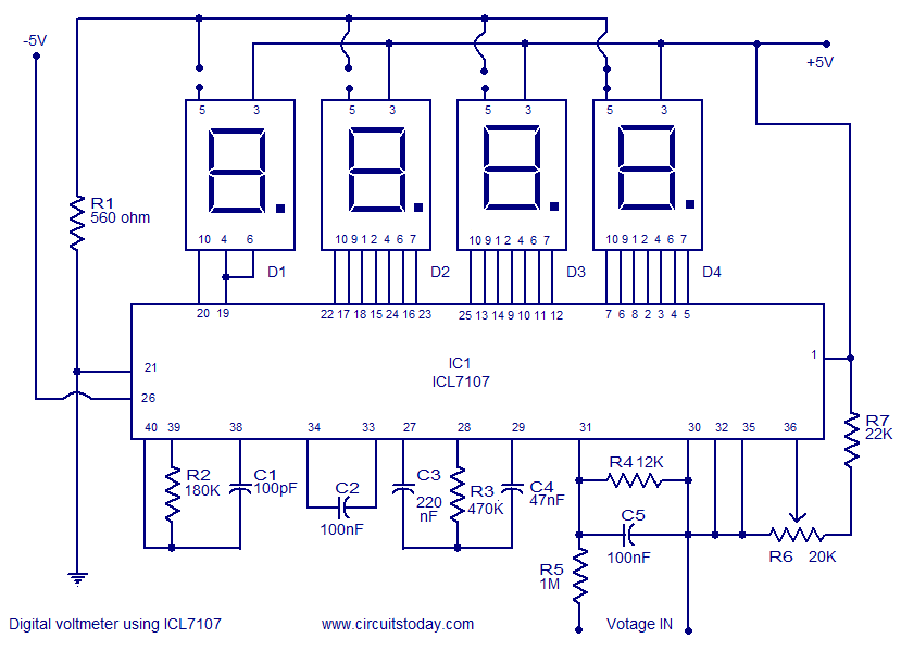
You will need to convert your AC voltage to RMS voltage then feed it to ICL7107. Datasheet has such a circuit on page 14. I attaching it here for your reference. The connection to the display is as the second attachment.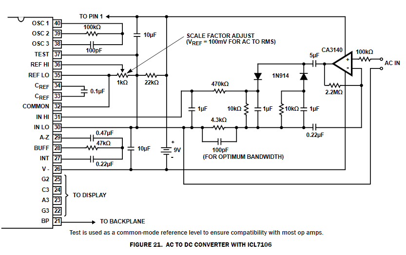
-
Thanks for introducing us to your project! I featured it on the blog. Good luck with your crowdfunding.
-
Welcome on board, feel free to post about your project and questions.
-
Electronics-Lab.com team is always looking for partnerships that will benefit our members and bring some valuable offer to all of you. This time we would recommend an Elektor yearly subscription for half the normal price. With this offer you will gain access to thousands of articles and hundrents of projects. This is an exlusive offer for electronics-lab members and to benefit from the offer you just have to enter E-LAB16 code on this form. The offer is valid for Elektor GREEN Membership and costs US $37.50 (€34.00 / £24.48) for a year. What you get: 6 Editions of Elektor Magazine (132 pages each) in PDF format Free access to all PDF editions of Elektor Business Magazine (approx. 6 per year) Unrestricted access to the Elektor 2000 - present day archive (thousands of articles!) Full access to over 750 Elektor Labs projects A minimum of 10% discount on all products at Elektor.com
-
I managed to open it with Sprint-Layout 5.0. Just rename the files in English and it will open.
-
OK.. So i have a difficult project...
admin replied to El Bruto's topic in Electronic Projects Design/Ideas
Hi and welcome to the forum, For what you describe you will need a light activated switch like this one: http://www.electronics-lab.com/project/light-and-dark-sensitive-switch/ This switch has adjustable sensitivity and with a little of experimentation you will manage to get the desired effect. It may be needed to add a kind of filter to the light sensor to reduce it's sensitivity even further as you need the switch to be activated in direct sunlight. You can also think to add a small "light pipe" to achieve the desired functionality. Hope that helps. -
leds Need help with a project
admin replied to jknightandkarr's topic in Electronic Projects Design/Ideas
How many digital IO lines do you have on your microcontroller? and how many LEDs do you want to drive? -
Here are two SPICE models found online that will simulate the main IC functions including:- a) bar/dot mode selection, dot mode carry for cascaded ICs, c) resistor-programmed hi/lo reference voltages, d) output current selection, e) non-grounded V- and divider ladder, f) independent V+ and Vled, g) leakage current of outputs, h) segment overlap and i) supply current variation with V+ and Vref output load. This model is build by user "alec_t" at electro-tech-online.com forum. LM3914.zip LM3914asc.zip
-
ELECTRONIC COMPONENTS TESTER
admin replied to pormobile's topic in Sell/Buy electronics - Job offer/requests
There are various components testers on ebay. You can check here: http://www.ebay.com/itm/M328-LCD-12864-Transistor-Tester-DIY-Kit-Diode-Triode-Capacitance-LCR-ESR-Meter-/141884915298?hash=item2108fffe62:g:uNYAAOSwGotWozua http://www.ebay.com/itm/TS-M8N-Transistor-Tester-Multi-functional-LCD-Backlight-Diode-Triode-Meter-N14D-/141813357437?hash=item2104bc1b7d:g:mGkAAOSwA4dWMDgN http://www.ebay.com/itm/ESR-Meter-Digital-Transistor-Tester-Diode-MOSFET-diode-Capacitance-MOS-PNP-NPN-/331509292666?hash=item4d2f7e5e7a:g:D4oAAOSwstxVCujN What exactly are you looking for? -
Hi, 2SD613 NPN has replacement BD243C, BD543C, BD801, 2SD866 BD243C KT819G 2SD633 is a NPN Darlington transistor and has replacement BD649, BD901, BDW73C, BDX53C BD649 2SD600 has replacement BD139, BD230, BD379, 2SD1684 BD139 2SB631 has replacement BD140, BD231, BD380, 2SA1184 BD140
-
It would be helpful if you provide a schematic on how the LM2596 are connected together.
-
Thanks for sharing your app with Elab. I featured it on the blog section: http://www.electronics-lab.com/hobbyist-electronic-inventory-system/
-
how to construct a mod-60 stopwatch counter?
admin replied to goblin85's topic in Electronic Projects Design/Ideas
The closest circuit to this one we have is this: http://www.electronics-lab.com/project/digital-stopwatch-0-60sec/ -
That's good news! I am happy to see that the issue is resolved now.
-
According to Sensirion datasheet here SHT31-ARP-B is an analog output temperature and humidity sensor with linearized and calibrated output. To interface it with Arduino you will have to measure the output voltage using an Arduino analog input and then convert the reading to humidity or temperature value based on the linear formulas found on the datasheet. These formulas are depended on the supply voltage of the sensor. I also found an Arduino library for this sensor here: https://github.com/winkj/arduino-sht you may find it useful.
-
Sure it can be, you only have to feed an AC signal to it's input (form a transformer for example) and measure it's output using an oscilloscope. Oscilloscope probe and input will provide some load to the rectifier and thus you will be able to see the full wave rectification and determinate if the bridge is working.
-
I have increased attachment size to 25MB. You can try to upload it again here.
-
Ideas for Single AA and AAA batteries?
admin replied to ElectronMan1's topic in Electronics chit chat
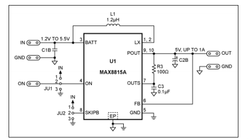
You could build a single cell LED boost driver like the third schematic here, using only 2 transistors. Or you can use ZXSC310 IC to build a boost LED driver working for as low as 0.8V input voltage like this schematic here: http://www.homemade-circuits.com/2012/05/1-watt-led-driver-circuit-using-single.html Alternative you can build a 1.2V to 5V boost DC-DC converter able to provide 1A max output current, like the second schematic here. For drained AA and AAA batteries you can build a Joule Thief that is able to draw the last available juice from the almost dead batteries. Like the first schematic here. http://www.homemade-circuits.com/2012/01/how-to-make-simplest-15v-bluewhite-led.html
.thumb.png.8b652b72ced23f00cd0f0d9a496cf96a.png)


.png.ce8886a6ead59a67c437702be0f6803f.png)