

audioguru
-
Posts
12,026 -
Joined
-
Last visited
-
Days Won
13
Content Type
Profiles
Forums
Events
Everything posted by audioguru
-
The datasheet for a u7805 voltage regulator says its minimum input voltage is 7V. The 9VAC transformer has a peak voltage of 12.7V and the bridge rectifier reduces it to 10.9VDC so it will be fine when filtered by the 1000uF capacitor. It will not harm a phone because the phone has the charging circuit inside it.
-
The capacitor will have AC across it, not DC so you cannot use a polarized electrolytic capacitor. I could not find a film capacitor rated at 47uF/400VAC anywhere. They were available 60 years ago, were very large and very expensive. But transformers are inexpensive and are available everywhere today.
-

I'm struggling to understand the function of transistors
audioguru replied to Sherldonnnn's topic in Theory articles
The datasheet tells you that for this little transistor to saturate with a saturation voltage drop of maximum 0.3V when its collector current is 10mA then the base current must be at least 0.5mA so the ratio of collector current to base current is 10mA/0.5mA= 20. Most American little transistors (2N3904 for example) specify a ratio of 10 but most European transistors (BC547 for example) specify a ratio of 20. This is saturation where hFE (current gain) is not used. hFE is used for a linear amplifier with plenty of collector to emitter voltage so it is not saturated. It seems that you do not understand that the base-emitter of a silicon transistor is a silicon diode. It conducts a very low current when its voltage is about 0.5V and it conducts a normal operating current of about 0.5mA when its voltage is 0.7V. Some transistors have a base to emitter voltage of 1V at a fairly high current. The base to emitter voltage changes when the temperature changes. You talked about applying 5V directly to the base of a transistor. The current would be so high that the transistor will explode (if the power supply can produce the very high current). -
Digital Ac voltmeter Using 7107
audioguru replied to Suresh mano's topic in Electronic Projects Design/Ideas
300VAC has a peak of 424V that will arc across an ordinary 100k resistor and destroy any opamp. Use a high voltage 100k resistor, a voltage divider and a voltage clamp that limits the opamp input voltage. -
What's the difference between MC14046B and CD4046?
audioguru replied to Barbra's topic in Datasheet/Parts requests
www.datasheetarchive.com has the datasheets from two manufactures of the very old CD4046A. Of course they also have the datasheets of the improved CD4046B, MC14046B and HEF4046B. -
Digital Ac voltmeter Using 7107
audioguru replied to Suresh mano's topic in Electronic Projects Design/Ideas
The ICL7107 is very old and has problems with accuracy when it warms up. The ICL7107S is an improved one. Its datasheet has a circuit that is recommended by the manufacturer. -
What's the difference between MC14046B and CD4046?
audioguru replied to Barbra's topic in Datasheet/Parts requests
About 53 years ago the CD4046A was introduced but it had many problems. It was replaced a few years later by the improved CD4046B and MC4046B and HEF4046B. Your CD4046A must be one of the very old ones with problems. Look on the datasheets of an A and of a B to see the differences. -
I think the inductance of the load is producing a big spark in the relay contacts that welds them shut. Use a relay made to switch higher current. Its contacts will be larger and its spring will be stronger.
-
The added TSOP1738 on the left side of the schematic is mounted where your remote can shine its modulated 38kHz IR on it. It demodulates the signal and modulates the added 555 38kHz oscillator that drives an added transistor and added IR LEDs mounted where the TV IR detector can see them.
-
The remote controls for my TVs work for 20 feet or more so yours should be fine at a distance of only a few feet. Maybe the battery in your remote is dead? I do not know what you call a "blaster". The TSOP1738 is not made anymore but there are similar ones available. Its output is the demodulated signal so the 555 is needed to create a new 38kHz carrier that the TSOP 1738 modulates. You might have interference between the original IR signal and the extender IR signal.
-
I revised the circuit, not the pcb. Others have done an Eagle pcb. I agree that there should be a place for storing the revised project.
-
12V at 1W is a current of only 1W/12V= 83mA. Is the current pot set higher than 83mA? When the voltage drops does the current regulation warning LED light up? Don't change parts without measuring what is wrong. The 2N3055 is simply an emitter-follower that has its base voltage about 0.62V higher than its emitter voltage at this low current. The driver transistor (I do not know which one you used) is also an emitter follower with its base voltage also about 0.62V higher than its emitter. Then for 12V output the output of opamp U2 should be about 12V + 0.62V + 0.62V= 13.24V. What is the base voltage of the driver transistor and the output voltage of U2 when the voltage drops? Does the unregulated supply at C1 measure 32V or more when the output voltage drops?
-
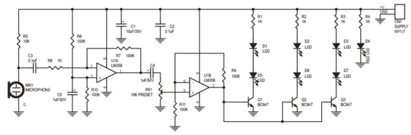
1) The first opamp is inverting with such a low input resistance of 1k ohms that it kills most of the signal from the higher resistance electret microphone. This opamp should be non-inverting with a much higher input resistance. 2) The coupling capacitor C4 between the opamps couples positive and negative AC to the input of the second opamp. But the maximum allowed negative input voltage is only -0.3V so the much higher negative part of the signal will probably damage the input. 3) The entire output current of the second opamp slams into the bases of the transistors without any current limiting that overloads the opamp and might damage the bases of the transistors.
-
The output voltage is supposed to be regulated then it should drop only 0.01V or less when you connect a load. Your output drops a few volts when connecting the load then it is not regulated and needs to be fixed.
-
The voltage regulation is provided by the reference voltage of 10.2V from U1, opamp U2, a driver transistor and an output transistor. The transistors are simple emitter-followers. then a few quick voltage measurements of the output with the malfunctioning occurring will show you what has failed.
-
The datasheet for your Mosfet will tell you its maximum rated temperature and its thermal resistance.
-
Simple arithmetic error. 5A x 0.1 ohms= 0.5V. 12V - 0.5V= 11.5V. 5A x 11.5V= 57.5W.The heatsink thermal resistance might be 1 degree C per Watt and the thermal grease might be 0.5 degrees C per Watt. The ambient might be 30 degrees C. Then the heatsink will be very hot and the chips inside the Mosfets might be hotter than allowed.
-
Nobody uses an old fashioned toxic Ni-Cad battery anymore. Your schematic has the polarities upside down. Usually positive is at the top and negative is at the bottom.
-
If the voltage on the (-) input of the opamp is lower than the voltage on the (+) input pin then the output will go positive which turns on the Mosfet more which should increase the voltage at the (-) input AND CANCEL THE INCREASE AT THE OUTPUT. The datasheet for the Mosfet (not ebay fakes?) shows a graph for a "typical one" with Vgs= 5.5V then current= 22A but some are more sensitive and some are less sensitive.
-
What is the part number of your Mosfets? It should be on your schematic. If the (+) input of the opamp is 0.8V and the current in the 0.5 ohm resistor is 1.6A then the (-) input of the opamp is also 0.8V. When you increase the battery voltage and the current tries to increase then it increases the voltage at the (-) input of the opamp that causes its output voltage to drop and turn down the current so that the current does not increase. Use an input of 0.8V and a fairly low battery voltage. Measure and post here the (+) input voltage, the (-) input voltage and the opamp output voltage. Then increase the battery voltage and measure and post them again.
-
If the input voltage does not change but the battery current reduces then the voltage across R4 also reduces and the LM324 opamp inverts and amplifies (minimum DC voltage gain is 25000 times) this voltage drop so that the current change is reduced to almost nothing. Check to make certain that the LM324 opamp output is not saturated as high as it can go (1.5V less than the power supply voltage) and that the gate voltages of the Mosfets are much higher than their source voltages (your schematic does not show a part number for the Mosfets) because most Mosfets need up to 10V.
-
The 22 ohm resistors are important. They prevent the Mosfets from oscillating at a high frequency.
-
You have not updated your schematic so maybe the LM324 opamp is still overloaded. Its output can source only 20mA so maybe the BD139 base current is higher.
-
Your interference is 60Hz but the fullwave rectifiers produce 120Hz so maybe your rectifiers are defective? 60Hz hum pickup from the wiring in your home? 60Hz picked up by a see-through diode (like a 1N4148) in the circuit being shined on by an AC light and acting like a photo-diode? You know what? The current regulator opamp is the only one using the -1.3V supply that is half-wave rectified so if C3 is defective or is upside down then it produces 60Hz interference. 'scope the -1.3V supply to see.
-
It is 60Hz from your electricity supply, not oscillation. Maybe you built the defective original circuit that has errors and many overloaded parts? The fixed and improved version is at the beginning of this thread. Maybe the tiny overloaded rectifier diodes failed or the transformer has burnt. The main filter capacitor has a value much too low. The original project cannot produce regulated 30V at 3A but maybe 25V at 3A instead or 30V at 1.5A. The original opamps are operating at a total supply voltage higher than their maximum allowed voltage and are noisy.
