

HarryA
-
Posts
451 -
Joined
-
Last visited
-
Days Won
23
Content Type
Profiles
Forums
Events
Everything posted by HarryA
-

Cherokee International SMPS Model# SP671-Y01A
HarryA replied to Edwin Navarathnam's topic in Power Electronics
There are used Cherokee International power supplies on ebay.com if that is any help. -
Yes, you are not the only one with that problem! See the circuit here: https://www.ebay.com/itm/Polk-Audio-DSW-PRO-500-Subwoofer-Amp-Plate-Not-Working-For-Parts-Repair/184441091699?hash=item2af18bb673:g:2~QAAOSwEkxfWY2A I was thinking you could get the correct parts from that one but no such good luck.
-
The eight leaded DIP is a " Low power offline switched-mode power supply primary switcher" see: file:///C:/Users/harry/AppData/Local/Temp/viper12a-e.pdf The larger diode P6? maybe a protection diode to protect from over-voltage. The two smaller diodes most likely are rectifiers used as part of the power supply. The question is what caused the fault that damaged the components. You need to investigate that before replacing the components else they may just blowout again. Try drawing out that part of the circuit to get insight into the circuit.
-
see: https://www.nteinc.com/semiconductors/ComplPr.php They list matched complementary pairs that maybe helpful like the NTE128/NTE129 at 80 volts and 1 ampere. And many others as well.
-
BCD calculator (urgent help in project)
HarryA replied to saimamuna's topic in Electronic Projects Design/Ideas
There is an article "Design Project2 - BCD Calculator" that maybe helpful. http://homepages.cae.wisc.edu/~ece352/fall02/old_project/p2.pdf -
Hunter College has a course in electronics that is online. That maybe helpful: Lessons are ElectronicsLab1.pdf through ElectronicsLab15.pdf http://www.hunter.cuny.edu/physics/courses/physics222/repository/files/pdf/ "Practical Electronics for Inventors" by Scherz and Monk is a very good book by not cheap.
-
The good news with the IR2153 is that it has a 50% duty cycle. The bad news is that you can not change it like in the 555 timer. You can change the frequency which would change the impedance at the coil/transformer which may give you some control of the output with the potentiometer PR1. Perhaps a larger potentiometer? Others may find the two schematics here easier to follow - without all the bells and whistles of this one. https://www.homemade-circuits.com/half-bridge-mosfet-driver-ic-irs21531d/#:~:text=Application Note%3A The main application of this IC,for driving mains CFL lamps from 12V supplies.
-
from Wikipedia: = (K+L)(K+M)(L+N)(M+P)(N+Q)(P+Q) = (K+LM)(N+LQ)(P+MQ) = (KN+KLQ+LMN+LMQ)(P+MQ) = KNP + KLPQ + LMNP + LMPQ + KMNQ + KLMQ + LMNQ + LMQ ----------------------------------------------------------------------------------------- K * N+LQ + LM*(N+LQ) K * N+LQ = KN+KLQ and LM*(N+LQ) = LMN+LMQ for the : (KN+KLQ+LMN+LMQ) for the fourth line multiply the third line by P and then by MQ from (P+MQ)
-
The capacitance reactance of the 100nf would be in the order of 26.6K so that could give you a current in the order of a few milli-amperes. The leakage current of the varistor is less than 20 micro-amperes for the 7D471K.
-
You can get timers that will go down to 1 second that maybe helpful. For example: "7-Day Programmable, Minimum Setting Time is 1 Second " https://www.amazon.com/NEARPOW-Multifunctional-Programmable-Countdown-Electrical/dp/B07QJ3K43N/ref=sr_1_118_sspa?dchild=1&keywords=electrical+timer&link_code=qs&qid=1596596156&sourceid=Mozilla-search&sr=8-118-spons&psc=1&spLa=ZW5jcnlwdGVkUXVhbGlmaWVyPUExRjRDTVBKVFVSMDhIJmVuY3J5cHRlZElkPUEwOTQwNzE4MUlLQVhNSk1WUzg5SyZlbmNyeXB0ZWRBZElkPUEwOTU5OTM3M0dLT0IwMTZDVVpSNyZ3aWRnZXROYW1lPXNwX210ZiZhY3Rpb249Y2xpY2tSZWRpcmVjdCZkb05vdExvZ0NsaWNrPXRydWU= You can also get 110 volt solenoids that would work off the timer. For example. https://www.amazon.com/Dormeyer-Laminated-Solenoid-Arcade-2005-M-1/dp/B00LNB2R5Q/ref=psdc_15731411_t1_B000CCNGMU If you need a dc solenoid you can get a small power supply that works with the timer. For example. https://www.amazon.com/ALITOVE-Converter-110-220V-Cigarette-Purifier/dp/B075FPQ2YQ/ref=sr_1_4?dchild=1&keywords=120+to+12+volt+converter&link_code=qs&qid=1596632952&sourceid=Mozilla-search&sr=8-4&tag=mozilla-20 And 12 volt solenoids are readily available: https://www.amazon.com/RuiLing-JF-0730B-Frame-Solenoid-Electromagnet/dp/B07QTKL4FV/ref=sr_1_23?dchild=1&keywords=12+volt+solenoid&qid=1596659237&sr=8-23 There are 12 volt solenoids that are designed for door latches if that is helpful. For the solenoids: 4.5N (newtons) equals 1 pound of force.
-
Perhaps you may find something useful here: https://www.electronics-lab.com/top-10-free-pcb-design-software-2019/
-
Most likely it is the manufacturer's part number. Perhaps you can find a schematic diagram?
-
Voltage drop: Circuit to control fans and leds
HarryA replied to Danirov's topic in Electronic Projects Design/Ideas
When the switch is closed in the debouncing circuit the input to the inverter is a logic 0 and the output a logic 1. Current flows from the battery supply of the inverter to its output. But the absolute maximum current rating for the output of a 74HC14 is only 24 ma. Do you really need a debouncing circuit? I wonder if you could replace the mosfet and debouncing circuuit with a 3 position switch; An On-Off-On. If not you may need a transistor between the inverter and the load. But you get a lost of 0.5 or 0.7 volts. Also the 100mfd capacitors are quite large for you circuit; charging the one through 2000 ohms will take awhile. Perhaps 1.0 mfd? -
"period and duty cycle" - electronics lab"
HarryA replied to spuddo's topic in Electronics chit chat
If you search for Arduino function or signal generator you will find some useful information. Like: https://circuitdigest.com/microcontroller-projects/arduino-waveform-generator -
"period and duty cycle" - electronics lab"
HarryA replied to spuddo's topic in Electronics chit chat
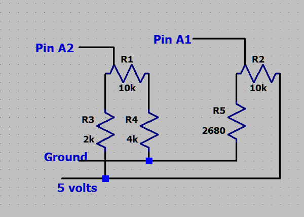
The URL is: https://www.youtube.com/watch?v=bIz9ektLunE Following the link from youtube does not lead to anything useful. The code has numinous errors. It would never run, for spuddo: This is a snapshot of the serial monitor displaying the output of the code below. This is the circuit that I used. The duty control on the left. The two resistors limit the range of the output. You do not want zero duty cycle for example. The period control on the right. The resistor limits the period from going to zero for example. The code: // // A rework of the code from the video: https://www.youtube.com/watch?v=bIz9ektLunE // void virtual_Scope(); int iDutyCyclePin = 2; //set input pin for the left pot = duty cycle int iPeriodPin = 1; //set input pin for the right pot = peroid int iLedPin = 13; //ser pin for output to LED //float fFrequency; //frequency = how many full periods per second or per 1000 millisedonds float fPeriod = 10; //value from the left pot float fDuty = 1; long int liPeriod, liDuty; int iDutyPercent; long int liHigh_Time, liLow_Time; void setup() { pinMode(iLedPin, OUTPUT); //declare ledpin as OUTPIN //Serial Port begin Serial.begin (9600); } void loop() { fPeriod = analogRead(iPeriodPin); //read the value from the right pot = period fDuty = analogRead(iDutyCyclePin); //read the value from the left pot = duty cycle //limit the range of the duty cycle to 20 to 80 percent of the period because that is what works! fDuty = (fDuty*9/10000) * fPeriod ; //with 5 volt supply liDuty = int(fDuty); //for printouts below liPeriod = int(fPeriod); //iDutyPercent = 100*liDuty/1024; //cal duty cycle as percent for serial monitor ???? iDutyPercent = 100*liDuty/liPeriod; //cal duty cycle as percent for serial monitor // fFrequency = (1000/float(liPeriod)); //cal frequency in units of Hertz for serial monitor ??? // liHigh_Time = liDuty*liPeriod/1024; //cal high = on time ??? liHigh_Time = liDuty; // high = on time liLow_Time = liPeriod - liHigh_Time; //cal low = off time Serial.println(); //new line Serial.print("period "); Serial.print(liPeriod); Serial.println(" milliseconds"); Serial.print("duty "); Serial.print(liDuty); Serial.println(" milliseconds"); Serial.print("on time "); Serial.print(liHigh_Time); Serial.println(" milliseconds"); Serial.print("off time "); Serial.print(liLow_Time); Serial.println(" milliseconds"); Serial.print(" duty cycle "); Serial.print(iDutyPercent); Serial.println(" % "); // Serial.print("frequency "); //what is frequency here? // Serial.print(fFrequency); // Serial.println(" Hertz"); digitalWrite(iLedPin, HIGH); //set the ledPin on delay(liHigh_Time); //pause the program for high_time in microseconds digitalWrite(iLedPin, LOW); //set the ledPin off delay(liLow_Time); //pause the program for low_time in microseconds virtual_Scope(); //display trace delay(4000); //slow down the scrolling } void virtual_Scope() { //display a line of pulses int iHighDashes, iLowDashes; int iCount; //let one dash = 30 ms iHighDashes = liHigh_Time/30; iLowDashes = liLow_Time/30; iCount = 60/(iHighDashes+iLowDashes); //try to make the lengths similar // Serial.println(String(iCount) + " "+ String(iLowDashes) + " " + String(iHighDashes) ); //new line for space at top Serial.println(); //space at top while (iCount--) { for (int i=0; i <iLowDashes; i++) { Serial.print("_"); } for (int i=0; i <iHighDashes; i++) { Serial.print("-"); } } Serial.println(); //space at bottom }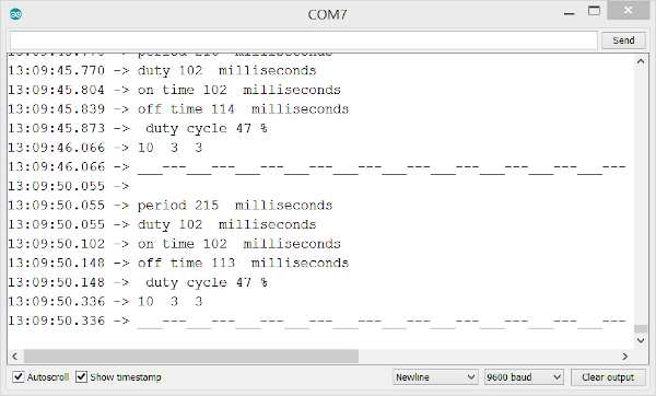
-
"period and duty cycle" - electronics lab"
HarryA replied to spuddo's topic in Electronics chit chat
Given what he shows in the video one can emulate the code easily. If that is what you would like. -
I gather one would need a microcomputer to interface one with the other. I take it the output one is not compatible with the input of the other?
-
or cleaner: String DisplayString = " "; //a blank string int percent1 = 0; int OldPercent = 0; void setup() { // Serial.begin(9600); //testing } void loop() { if( OldPercent != percent1 ) //do not scroll needlessly { //previous string - set the cursor to second line LCD.setCursor(0,2); LCD.print(DisplayString); //move previous line down //set the cursor to for new first line LCD.setCursor(0,1); if (percent1 > 50) { //new string DisplayString = "Moisture S1 : " + String(percent1) + "%" + " Irrigaion sistem ON"; } else { //new string DisplayString = "Moisture S1 : " + String(percent1) + "%" + " Irrigaion sistem OFF"; } //set the cursor for new first line LCD.setCursor(0,1); LCD.print(DisplayString); //new line to top of the LCD OldPercent = percent1; //set new percent } } //end loop the first "set the cursor for new first line" code is redundant; I can not see how to edit the code
-
Perhaps: String DisplayString = " "; //a blank string int percent1 = 0; int OldPercent = 0; void setup() { // Serial.begin(9600); //testing } void loop() { if( OldPercent != percent1 ) //do not scroll needlessly { //previous string - set the cursor to second line LCD.setCursor(0,2); LCD.print(DisplayString); //moves previous line down if (percent1 > 50) { //new string DisplayString = "Moisture S1 : " + String(percent1) + "%" + " Irrigaion sistem ON"; //set the cursor to for new first line LCD.setCursor(0,1); LCD.print(DisplayString); //new line to top of the LCD OldPercent = percent1; //set new percent } else { //new string DisplayString = "Moisture S1 : " + String(percent1) + "%" + " Irrigaion sistem OFF"; //set the cursor to new first line LCD.setCursor(0,1); LCD.print(DisplayString); //new line to top of the LCD OldPercent = percent1; //set new percent } } } //end loop
-
"Could a capacitor smooth the frequency? " If one does not know what is wrong with the system then one can not know what the affects of a capacitor would be. you have a 12 5kw diesel generator the generator outputs 120 or 240 volts at 50 or 60 hertz. the generator supplies the mains that has numerous outlets on the boat. the generator output is stable until you turn on the ac unit. with the ac running the voltage at the various outputs are no longer 50 or 60 hertz but varying in frequency 6: adding any load to an output corrects the problem. Is that correct?
-
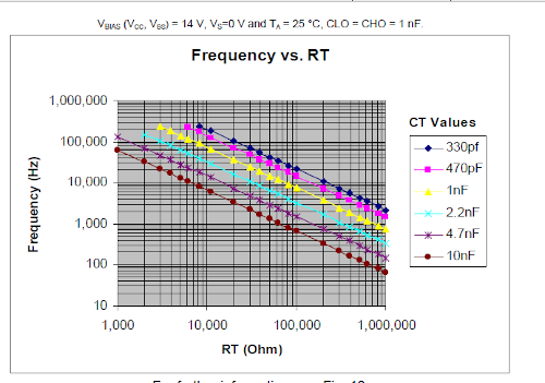
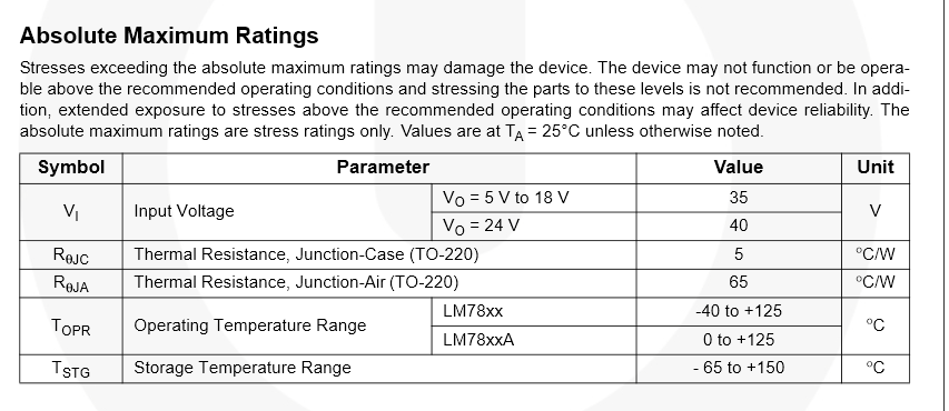
48 volts is above the absolute voltage for this voltage regulator: 35 volts maximum:
-
In that type of air conditioner the input ac voltage is converted into dc via a power supply. The dc voltage is converted (inverted) into variable frequency ac. The frequency depends on the demand on the unit. A microcontroller samples the ambient air temperature and adjusts the speed of the compressor motor via the frequency of the ac applied to the compressor motor. Invert versus convert is interesting: Inverter - dc to ac converter - ac to ac (transformer, etc) converter - dc to dc (potentiometer, etc) power supply - ac to dc
-
see: http://starseedsportal.org/tag/stephen-dickens-magnesium-water-copper-battery/ plus other sites; search on "stephen dickens water battery" Also see Voltaic pile at: https://en.wikipedia.org/wiki/Voltaic_pile
-
I have not used varistors but not letting ignorance slow me down. The V20E14AUTO is a 16 volt MOV. Voltage Rating DC: 16vdc Varistor Voltage: 22 volts this is where the varistor starts to conduct at 1 ma. Varistors draw some small current always Clamping Voltage: 43 volts the voltage any spike is truncated to. Peak Surge Current: 20 amperes. Surge Energy Rating: 28 joules. 28 watts-1 second, 56 watts-500 ms, etc Unlike Zener diodes that fail as an open circuit varistors fail as a short circuit so in some cases a fuse is used with them. Most likely on the larger ones.. see: https://www.mouser.com/ProductDetail/Littelfuse/V20E14AUTO?qs=%2Fha2pyFadugE%2FoOLoA7J9TCvi67Mtc%2F%2FOVMAqZDk45RR%2F7GD1QKNkA%3D%3D or: https://www.digikey.com/products/en?mpart=V20E14AUTO&v=18 That is my best guess; perhaps someone else has experience with varistors? "The MagLock Draws 420mA 2 12 Volts, The panels power supply provides 500mA @ 14.3 V " Do you need to reduce the 14.3 volts to 12 volts?
-
Wikipedia has a well written article on operational amplifier applications. see: https://en.wikipedia.org/wiki/Operational_amplifier_applications#Non-inverting_amplifier
