HarryA
-
Posts
451 -
Joined
-
Last visited
-
Days Won
23
Content Type
Profiles
Forums
Events
Everything posted by HarryA
-

Parts suppliers
HarryA replied to jknightandkarr's topic in Sell/Buy electronics - Job offer/requests
Well already having ruined jknittandkarr's thread - sorry jknittandkarr. But another place to spent more money beyond amazon.com and ebay is at the goodwill: see "computers and electronics" off: https://www.shopgoodwill.com/listings/ Don't bid on the solar panel! I am watching -
Parts suppliers
HarryA replied to jknightandkarr's topic in Sell/Buy electronics - Job offer/requests
Good question. I test them with my 4 of 5 stars Chinese tester I never buy anything very expensive that I could not toss out. https://www.amazon.com/gp/product/B01M0UXHYY/ref=oh_aui_detailpage_o02_s00?ie=UTF8&psc=1 -
Parts suppliers
HarryA replied to jknightandkarr's topic in Sell/Buy electronics - Job offer/requests
Yes some people have problems with parts from China but I buy a lot for China. And I never have any problems. I have two items in the "China queue" now. I call it bypassing Wal-Mart and NTE -
Parts suppliers
HarryA replied to jknightandkarr's topic in Sell/Buy electronics - Job offer/requests
Go directly to the source: http://www.ebay.com/itm/10pcs-0-8-inch-1-digit-led-display-17-seg-Alphanumeric-Common-anode-BLUE-/311641497467?hash=item488f47df7b:g:nBAAAOSwsB9V87Ec That is where they are all made anyway. -
Automatic turn on/off power supply transformer - primary winding
HarryA replied to HackoBoy's topic in Projects Q/A
(1)"I have an idea, but I do not know how." What is your idea? (2)"I noticed that the charger for my phone if the phone is not turned on to charge - it does not consume anything. But when I turn on the micro usb connector - then begins to consume." Find; a statement of fact. (3)"Now fit a box that will convert unbalanced audio signal into balanced. But the transformer can not fit in the box of the device and the target mount it in an external box. I do not want a permanent transformer is plugged in. " What is the relationship between sentence (2) and sentence (3)? What are trying to do in sentence (3)? -
A modern day 0 - 30V, 0 - 3A Linear Power Supply?
HarryA replied to repairman2be's topic in Projects Q/A
I tried to buy "30v 10A 110V precision variable dc power supply ..." for 6.97$ and free shipping but it would not let me "buy it now". To good to be true? Worth that as a coffee warmer! http://www.ebay.com/itm/30V-10A-110V-Precision-Variable-DC-Power-Supply-Clip-Cable-Digital-Adjustable-S/222418872649?_trksid=p2047675.c100005.m1851&_trkparms=aid%3D222007%26algo%3DSIC.MBE%26ao%3D2%26asc%3D41394%26meid%3D98314beb8bcf41c2956f228cf09493ad%26pid%3D100005%26rk%3D5%26rkt%3D6%26sd%3D391694935441 -
A modern day 0 - 30V, 0 - 3A Linear Power Supply?
HarryA replied to repairman2be's topic in Projects Q/A
I understand. My electronic books are old enough to vote. Also I find it cost so much for the components that it is far cheaper to buy than build. For example see: http://www.ebay.com/itm/30V-5A-DC-Power-Supply-Adjustable-Dual-Digital-Variable-Precision-Lab-Grade-110V-/391378270581?hash=item5b1ff67975:g:zwcAAOSwUKxYiV76 -
A modern day 0 - 30V, 0 - 3A Linear Power Supply?
HarryA replied to repairman2be's topic in Projects Q/A
If you look at [Projects] at the top of the page you may find something helpful: Projects->Power. (Odd there is no link back to the forum page from those pages?) -
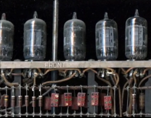
I am thinking these are color coded capacitors. Photography of part of an early computer.
-
There are Cannon FH7- xxxx stepper motors that are 24 volts and 1 ampere it that is any help.
-
basic electronics lab experiment single stage CE amplifier
HarryA replied to pvshah's topic in Electronics chit chat
If you list the values of the resistors and the type of transistor then one could help you. -
I need a critical help in designing a magic toy
HarryA replied to salvazero's topic in Electronic Projects Design/Ideas
You ask for a lot! Start with Ebay.com for transmitters and receivers: see: http://www.ebay.com/itm/Mini-88-108MHz-FM-Transmitter-Module-Wireless-Microphone-Dictagraph-Interceptor/141659602950?_trksid=p2047675.c100005.m1851&_trkparms=aid%3D222007%26algo%3DSIC.MBE%26ao%3D2%26asc%3D40832%26meid%3D5caec1e4bbe74e2fa065b6379434198a%26pid%3D100005%26rk%3D2%26rkt%3D6%26sd%3D111649741072- 1 reply
-
- 1
-

-
how to make a mailbox light? guys
HarryA replied to Barbra's topic in Electronic Projects Design/Ideas
http://www.talkingelectronics.com/projects/SolarLight/SolarCharger-2.html -
I got a package of 3 boards and jumper wires via Amazon.com and they are crap! Very difficult to insert the jumpers into. I also left my review of them and it was not nice. Also I saw a video on youtube.com where the instructor instructed the students to use needle noise pliers to insert the jumpers into the same type of breadboard. beware of: https://www.amazon.com/UCEC-830-Point-Solderless-Circuit-Breadboard/dp/B01EL7BNEO/ref=sr_1_36/157-6188074-9414127?s=pc&ie=UTF8&qid=1484020623&sr=1-36&keywords=bread+boards
-
You are not their only customer, they put you on the end of the queue. It takes me about 3 weeks to get electronic gear from China and it is already make!
-
You points are well made; thanks. On day one I found two voltage boosters on Ebay that gave more than 100 volts so I ordered both of them from China. The first one I received was a 12v dc to 200 v dc. After connecting it up and adjusting it for 200 v I put a 100k resistor across the output and got 2 volts output! It took a one mega-ohm load to keep 200 v. The second one (12v dc to 220 v ac) works well. I connected it to the 220v to 120v step down transformer and into a full wave bridge rectifier with a 100mfd capacitor and got 140 v dc; 9.6 volts input. With a 8.4 v NiMH rechargeable battery I get 128 v dc. So I am happy with that and very surprised that the 50/60 hertz transformer works at all!
-
Hello from cold and snowy NE PA, In my quest to convert 9 - 12 volts dc into 140 volts dc I purchased a "40W DC-AC 12V To 220V Step-up Transformer Boost Module Inverter" via Ebay. I also purchased a 220 volt to 120 volt 50-60 hertz step down transformer; the type travelers use. But the inverter's output is 38.4k hertz! So my transformer is useless here. I am wondering if one can find a transformer that will handle that frequency and is two to one? I am driving a class D pulse amplifier that outputs 100 Volts peak at a current of 0.10 amperes max. The pulse is 0.4 ms duration at and interval of 2 ms. So I am thinking that I need: 100v * 0.10 * 0.4/2 = 2.0 watts for the amplifier output so I am thinking about 10 watts for the amplifier and the conversion from 120 ac to 140 dc. "
-
100V 10A constant charging current circuit ?
HarryA replied to vanbutan's topic in Electronics chit chat
It maybe cheaper to buy one? http://www.ebay.com/itm/1200W-100V-DC-Switching-power-supply-for-LED-Strip-light-AC-to-DC-power-supply-/182370960410?hash=item2a7628041a:g:sukAAOSw6aVUn95M -
Is there some way to get read of the %^^*)(*^ pop up with " would you like to receive notifications.... ? I DO NOT WANT ANY!
-
You could charge the cap. with solar cells during the day and light an LED at night? No batteries required! see: http://www.ebay.com/itm/Maxwell-D-Cell-Power-350F-350-F-Farad-2-7V-Super-Capacitor-Cap-Ultra-Battery/281173041415?_trksid=p2047675.c100009.m1982&_trkparms=aid%3D888007%26algo%3DDISC.MBE%26ao%3D1%26asc%3D38530%26meid%3D4d48fa267f404223bb70c8c93e334efc%26pid%3D100009%26rk%3D1%26rkt%3D1%26sd%3D161240113620 man that is some url!
-
Most likely you have a few screws loose John see: http://en.allexperts.com/q/Electrical-Wiring-Home-1734/2009/6/Circuit-reads-60-volts.htm also search on: "electrical problem 60 volts on 120" good luck. addendum: As this a common problem could a poor connection between copper (or better yet corroded copper; copper oxide) and plated steel act as a diode and the the results (at very low current) is a half wave rectifier? That would yield the 60 volts rms. ref: http://www.tutorvista.com/physics/half-wave-rectifier-calculation
-
Thanks for the reply. I have a a 400 microsecond pulse every 20 ms that I wish to amplify. I need about 100 volts so I an thinking I need a 150-200v transistor. I need to preserve the varying amplitude so I can not just emulate it with a switching transistor. Speaking of transformers; I tried amplifying it with a 2n7000 n channel MOSFET using an audio transformer in reverse (input into the 8 ohm windings ) but I could not get a decent output pulse in spite of using various combination of diodes. HarryA \../ To close this out. I found mouser.com to be helpful as they have a system of filters that makes it easier to find what you want - with some effort. I ordered the n-channel ZVNL120 eMOSFETs from then; 200v and 120ma. The book "Electronic Devices and Circuits" by "Schaum's easy outlines" has good information on circuit design using bipolar, FETs, and MOSETs tranistors.
-
Hello from NE PA, Where do you all find data on MOSFET transistors? I look on ebay for MOSFETs but most do not have specs so you have to search for a data sheet, download it, open it, and find it's not what you want! I am looking for an n channel eMOSFET for a class D amplifier that has 150 to 200 volt drain to source. Some 20 to 40 ma for current. I find lots of power switching MOSFETs references. Are there any good books on using MOSFET transistors? thanks in advance, HarryA
-
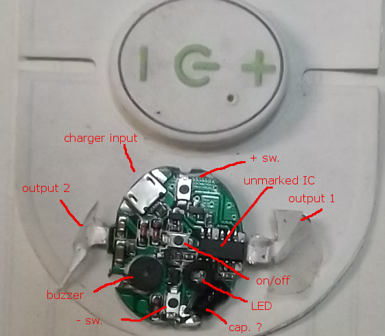
Hello from NE PA, A question for you. How to TENS machines generate 40 to 60 volts from say 4.2 volts without using a coil or transformer? Pictured is a TENS circuit that is about 1.26 inches by 1 inch. The battery is on the reverse side of the board. thanks in advance, HarryA