HarryA
-
Posts
451 -
Joined
-
Last visited
-
Days Won
23
Content Type
Profiles
Forums
Events
Everything posted by HarryA
-
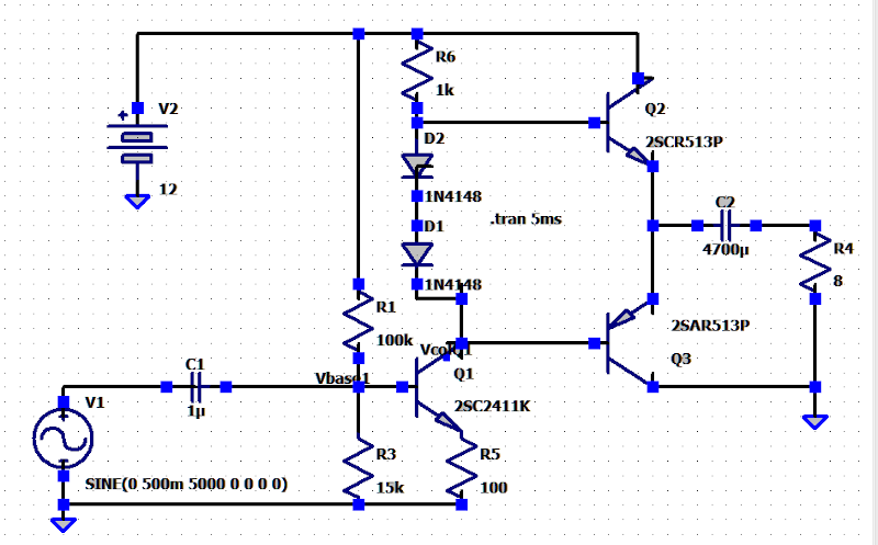
"LTspice® is a high performance SPICE simulation software, schematic capture and waveform viewer with enhancements and models for easing the simulation of analog circuits." There are numerous tutorials and manuals for LTspice online. You can import component models not in its library into it using other spice models. see: https://www.analog.com/en/design-center/design-tools-and-calculators/ltspice-simulator.html A circuit in LTspice:
-
 Are you using the type of actuators that have brushed motors ? I gather they have switches that limit their travel in each direction. Also I see that folks are building controls using microcomputers like the Arduino but that seems like the hard way of getting one. Are your actuators similar to this one? https://www.amazon.com/dp/B079G1NZHT/ref=emc_b_5_t?th=1 also look at these: https://www.progressiveautomations.com/collections/control-boxes? I gather their 30 amp dual controllers are only 15 amps each. They have joysticks here: https://www.progressiveautomations.com/products/rc-08 This is like what you have now? https://www.amazon.com/Forward-Reverse-Module-Actuator-Reversing/dp/B0881N7F4M/ref=sr_1_53?crid=25CETHKMKA6N1&keywords=linear%2Bactuator%2Bcontroller%2B12v&qid=1637517171&s=industrial&sprefix=Linear%2BActuator%2BController%2Cindustrial%2C232&sr=1-53&th=1
 -
ESP8266
-
Balanced to double unbalanced converter
HarryA replied to Ivan B.'s topic in Electronic Projects Design/Ideas
It is very difficult to help someone with home made circuits as there so many things that can go wrong. Like bad components, poor solder joints, miss read schematics, etc. The transformer you are using has two secondary windings of 6 volts rms (8.4 volts peak) each, what are you getting for voltage out of your power supply? I gather you need 15v dc. -
One could use a pair of Arduino mega 2560 microcomputers each has 16 analog inputs. Using two boards each monitoring 10 cells. As each cell is measured relative to ground from the its first cell the additional voltage would indicate the voltage on that cell, That is if the voltage at the 5th cell where say 6.5v to ground and the 6th cell where 7.9v the computer would "know" that cell is at 1.4v and thus charged. It would switch it out of the circuit and replace it with a shunt resistor. Also there are Arduino devices to monitor current up to 5 amperes using a Hall effect device.
-
In the circuit above the 2SD1805 is an NPN not a PNP as required. The TL431 is a precision programmable reference. I could try the circuit in the simulator if I can find a spice model for the TL431 or otherwise simulate it. I see: "The 2SB1205 is a complementary PNP transistor for the 2SD1805." Characteristics of 2SB1205 Transistor Type: PNP Collector-Emitter Voltage: -20 V Collector-Base Voltage: -25 V Emitter-Base Voltage: -5 V Collector Current: -5 A Collector Dissipation: 10 W DC Current Gain (hfe😞 100 to 400
-
Tenergy claims to have a Nicd charger for 12 - 24v but I could not find it on their web site. They are less expensive on Amazon.com then on their site. I would think it less expensive than building one from scratch if it is under 100$. They require an external power source. I use a Tenergy to charge my quadcopter's battery. As you are fabricating you own battery you could set it to charge say 10 cells at a time but that requires 8 charges; mine will do 15 cells. see: https://power.tenergy.com/chargers/for-battery-packs/12v-24v-nimh-nicd/
-
Can you use a variac transformer? This company sells some large ones. See "Variable Transformer Selection Guide" here: https://variac.com/pages/variable_transformers.htm search on 6020-3p for example.
-
My robot shows an error on the left wheel
HarryA replied to Holy Hathaway's topic in Electronic Projects Design/Ideas
If it works in another unit why do you think it is damaged? Perhaps the fault lies with the error sensing circuit. A fault that arises with vacuum cleaner power heads is that a string, etc. gets wound around the wheel axis impeding the wheel. There are videos related to this type of problem on youtube: for example see: https://www.youtube.com/watch?v=kqq6Ezilky4 In regard to the mosfet; if there is a voltage at the gate of 3 to 4 volts or more the voltage across the mosfet should be less the supply voltage. If not that may mean the mosfet is opened - not conduction current. If I were to build a robot I would buy one to use as a base; https://shopgoodwill.com/categories/listing?st=robotic cleaner&sg=&c=&s=&lp=0&hp=999999&sbn=&spo=false&snpo=false&socs=false&sd=false&sca=false&caed=11%2F17%2F2021&cadb=7&scs=false&sis=false&col=1&p=1&ps=40&desc=false&ss=0&UseBuyerPrefs=true&sus=false&cln=1&catIds=&pn=&wc=false&mci=false&hmt=false -
Optical Network Terminal (ONT) Design
HarryA replied to diego gutierrez's topic in Electronic Projects Design/Ideas
For the RTL9602C see: https://www.worldwayelec.com/pro/richtek-technology-corporation/rtl9602c-va4-cg/5335833 It is also listed here: https://www.netcomponents.com/sitemap/RTL9602C-VB-CG.html The BD16A62 transformer is listed here: https://lcsc.com/search?q=bd16a43 and here: https://www.x-on.com.au/keywordsearching?kword=bd16a43 -
Looking for an Optical RPM module
HarryA replied to Kerrowman's topic in Electronic Projects Design/Ideas
You can roll your own laser tachometer and mount it however you wish: https://www.youtube.com/watch?v=0UqHNrqmTRU -
See section [047] here: https://blog.podkalicki.com/100-projects-on-attiny13/ else you could rewrite the stepper.cpp library file for the ATtiny13A.
-
I could not find any information on the Sonico Eastern er337. I take it that it runs off the 12 volt car battery. Also the output to the speaker is two wires so that must be mono not stereo output. You could try it and see how well it works. As the input is for a microphone it expects low level inputs.
-
How to use 74HC595 Shift Register with Arduino?
HarryA replied to sushawn's topic in Power Electronics
how-to-use-the-74hc595-shift-register-with-arduino -
Sorry I can not help you. There is a site that discusses a similar problem "How to set up Keil Logic Analyzer to Read Specific Pin?" Here: https://electronics.stackexchange.com/questions/348122/how-to-set-up-keil-logic-analyzer-to-read-specific-pin Also there is some information on Youtube on the Keil analyzer that maybe helpful.
-
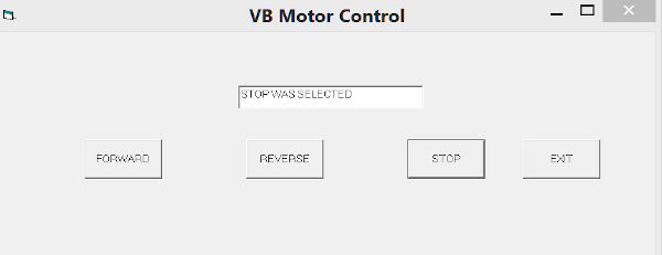
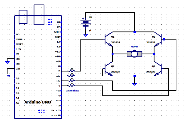
You can use the serial commucations control in VB (Visual Basic) to commucate with an Arduino board. This allows one to make a more formal interface to the board. The serial comm control is found in project/component/Microsoft Comm Control 6.0 in the VB visual studio. Selecting it adds it to the tool box. It can then be dragged on to the form. Its symbol looks like a telephone. In this example an Arduino board is controlling an electric motor via an H bridge circuit. The inputs to the bridge circuit are from pins 4, 5, 6, and 7 from the Arduino board. In the VB code below, the serial interface is setup on loading the form. And four buttons are added: forward, reverse, stop, and exit. On selecting a button it sends a signal to the board which in turn outputs signals to pairs of pins to the transistors in the H bridge. A more practical interface would have code to ask the user which comm port to connect with. ' VB 6 -motor control via Arduino UNO/Mega 2560 Private Sub Form_Load() MSComm1.RThreshold = 3 MSComm1.Settings = "9600,n,8,1" MSComm1.CommPort = 6 'use the one IDE uses MSComm1.PortOpen = True MSComm1.DTREnable = False Text1.Text = "" End Sub Private Sub FORWARD_Click() Text1.Text = "FORARD DIRECTION WAS SELECTED" MSComm1.Output = "f" End Sub Private Sub REVERSE_Click() Text1.Text = "REVERSE DIRECTION WAS SELECTED" MSComm1.Output = "r" End Sub Private Sub STOP_Click() Text1.Text = "STOP WAS SELECTED" MSComm1.Output = "s" End Sub Private Sub EXIT_Click() MSComm1.Output = "s" 'make sure motor is stopped Unload Me End Sub On the board side the Arduino code waits for a serial signal then sets or clears the outputs as required. //this program receives commands via the visual basic program running on the pc //based on: Patel, Ujash.: "Arduino + Visual Basic 6.0:Make your own software to control Arduino Robot //outputs to the four transistors in the // H bridge controling the motor int pin7 = 7; int pin6 = 6; int pin5 = 5; int pin4 = 4; void setup() { Serial.begin(9600); pinMode(pin7, OUTPUT); pinMode(pin6, OUTPUT); pinMode(pin5, OUTPUT); pinMode(pin4, OUTPUT); //all low/off = stopped digitalWrite(pin4,LOW); digitalWrite(pin5,LOW); digitalWrite(pin6,LOW); digitalWrite(pin7,LOW); } void loop() { if (Serial.available()) { int command = Serial.read(); //all low/off = stopped digitalWrite(pin4,LOW); digitalWrite(pin5,LOW); digitalWrite(pin6,LOW); digitalWrite(pin7,LOW); if (command=='f') //forward { digitalWrite(pin7,HIGH); digitalWrite(pin4,HIGH); } if(command=='r') //reverse { digitalWrite(pin5,HIGH); digitalWrite(pin6,HIGH); } //we initialize to stop with all LOWs above if(command=='s') command = 's'; //dummy statement }//end if(serial) }//end Loop() This project is based on Ujash Patel's book: "Arduino + Visual Basic 6.0: Make your own software to control Arduino Robot" . Amazon.com Kindle Edition.
-
Can I replace MPXV7002DP transducer by MPXV7002DPT1?
HarryA replied to Holy Hathaway's topic in Projects Q/A
This site gives the MPXV7002DPT1 as an alternative to the MPXV7002DP see: https://www.apogeeweb.net/circuitry/mpxv7002dp-transducer-datasheet-features-pinout.html#product-overview This one has a list of exact alternatives also: https://www.newark.com/nxp/mpxv7002dpt1/pressure-sensor-2-to-2kpa-sop/dp/28X3717 -
The 2sc5200 is a large "High-Fidelity Audio Output Amplifier" it would be used as the last stage in a mullti-transistor amplifier. What is the input in to your amplifier? Consider using an op amplifier that would give you a simple amplifier that could use a low level input and give you 5 watts or more output. The LM383/TDA2002 is an 8 watt power amplifier that uses 5 capacitors and 2 resistors. You can drive a 4 ohm speaker directly with It. As it is an old op amp you may find a more modern version of it. The LM383 is available on Ebay.
-
You can find information on the subject at the NI subforum: https://forums.ni.com/t5/Instrument-Control-GPIB-Serial/bd-p/140?profile.language=en The NI discussion forum starts here: https://forums.ni.com/t5/Discussion-Forums/ct-p/discussion-forums?profile.language=en
-
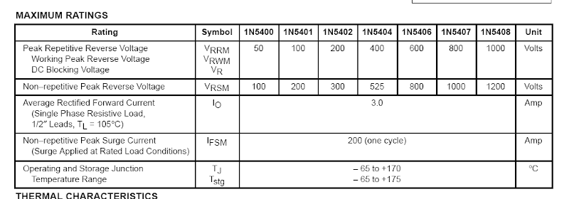
You can use the 1N5408 in place of the 1N5404 and you can use the 1N5404 in place of the 1N5408 if the voltage is less than a peak reverse voltage of 400 volts.
-
Can you copy this code and paste it into the IDE and get it to compile? Be sure to select nano in the IDE tools->board = "Arduino Nano". This is for an ultrasonic device but for testing you do not need the device: #define trigPin 9 #define echoPin 10 long duration; int distance; long firstoff; int distancefirst; void setup() { Serial.begin(9600); pinMode(trigPin, OUTPUT); pinMode(echoPin, INPUT); delay(1000); digitalWrite(trigPin, HIGH); delayMicroseconds(10); digitalWrite(trigPin, LOW); firstoff = pulseIn(echoPin, HIGH); distancefirst = firstoff*0.034/2; // cm digitalWrite(trigPin, LOW); delayMicroseconds(2); digitalWrite(trigPin, HIGH); delayMicroseconds(10); digitalWrite(trigPin, LOW); duration = pulseIn(echoPin, HIGH); distance= duration*0.034/2; // cm //distance = duration * 0.0133 / 2; // in Serial.println(distance); delay(1000); Serial.println(distancefirst); if (distance <= distancefirst - 5) { tone(3, 500, 500); delay(500); tone(3, 800, 500); delay(500); delay(50); } } It is the first project from: https://create.arduino.cc/projecthub/projects/tags/nano
-
Try https://search.yahoo.com/ I found all four that way!
-
Hello everyone, good afternoon. I am new here. And I've been researching a common defect in a polk dsw pro5000 board. Whoever has the schematic diagram or gives me the list of the following components, I'm very grateful. D4 (?) C7 (?) Diodo? D5 (?) That is a 5000 not a 500? see: https://hardforum.com/threads/polk-audio-dsw-pro-500-no-power.1978149/
-
What can be used to increase the LM3914N voltage
HarryA replied to Tessie Swift's topic in Electronic Gadgets
If you download the lm3914.pdf file from TI you will see directions on how to program the current. I believe it is sinking current not supplying voltage. Also there are numerous web sites on how to build an LM3914 dot/bar display driver circuit. See: https://www.ti.com/product/LM3914 For others; this is what it looks like: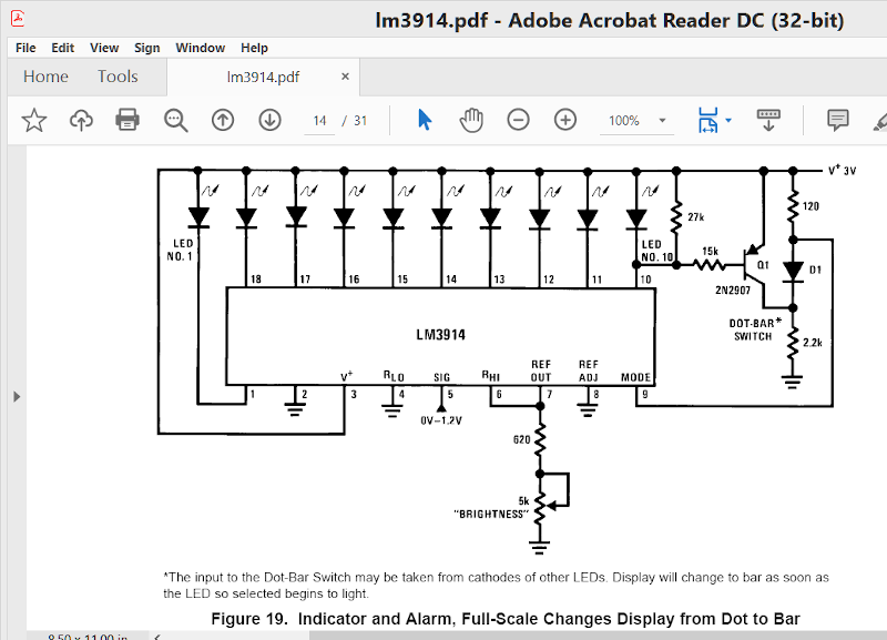
-
Advice Please On this amp design
HarryA replied to john121's topic in Electronic Projects Design/Ideas
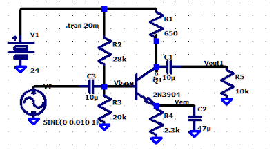
This works well in the simulator using the transistors shown: