I actually think that it is counter intuitive to put the resistance of the coils into the internal resistance of the voltage sources, tell me your thoughs on this!
Sadly, that's the case, unless you can source bigger coils with lower resistance but a similar number of turns.
Driving a 15W load from a 30V supply needs 0.5A current, but 0.5A would drop 25V across a 50 Ohm coil resistance.
I'll fit the coils I have, in place, and then see what the most amount of voltage I can get on each of the four coils before the rectifier max speed never been to max speed yet!!! and take more readings!
and you're forgotten one thing, the 15watt load is driven by four coils that have 50ohm each! and each produce 40voltAC! so DCvoltage is what? and then there's the smoothing cap bank
Sadly, that's the case, unless you can source bigger coils with lower resistance but a similar number of turns.
Driving a 15W load from a 30V supply needs 0.5A current, but 0.5A would drop 25V across a 50 Ohm coil resistance.
so how would this play out if the, the 15watt load from a 30volt supply needs 0.5 amps, across the four coils that 0.125amps each coil, 50ohm * 0.125Amp, the drop across each coil would only be 6.25volts across the 50 ohm coil resistance!
could I wire the coils in parallel to quater the resistance? or wire the two coils that are on the back of the machine in parallel and the two coils on the front of the machine in parallel that would halve the resistance!
so I tried to put the coils that are the same phase in parallel and the result is better, not perfect but better, about 27volt. I take that back! nevermind
I haven't forgotten. The coils aren't in parallel. The coil voltages are not in phase (they're in quadrature in the sim, but in the real world they would be time-separated according to the coil spacing around your machine).
I haven't forgotten. The coils aren't in parallel. The coil voltages are not in phase (they're in quadrature in the sim, but in the real world they would be time-separated according to the coil spacing around your machine).
can I put the coils that are in phase ie the two at 0 degrees and then the two at 120 degrees this would halve the resistance, thanks
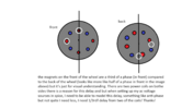
the ones at the back of the wheel are in black and the white lag by 120 degrees the wheel turns anticlockwise I hope you can understand the diagram, thanks!
I haven't forgotten. The coils aren't in parallel. The coil voltages are not in phase (they're in quadrature in the sim, but in the real world they would be time-separated according to the coil spacing around your machine).
so I have a spare flywheel and just bought some new magnets going to try a different configuration next time and put the magnets all in phase so that I can parallel the coils but not giving up on this wheel just yet!
")