8 Channel Inductive Load Driver Arduino Shield
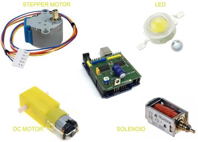
The 8 Channel Driver Arduino UNO Shield is designed to enable users to switch inductive loads for up to 800mA each channel and up to 24V DC with no heat-sink needed. It is ideal for such applications as driving 2x unipolar stepper motors, solenoids, relays, and small DC motors.
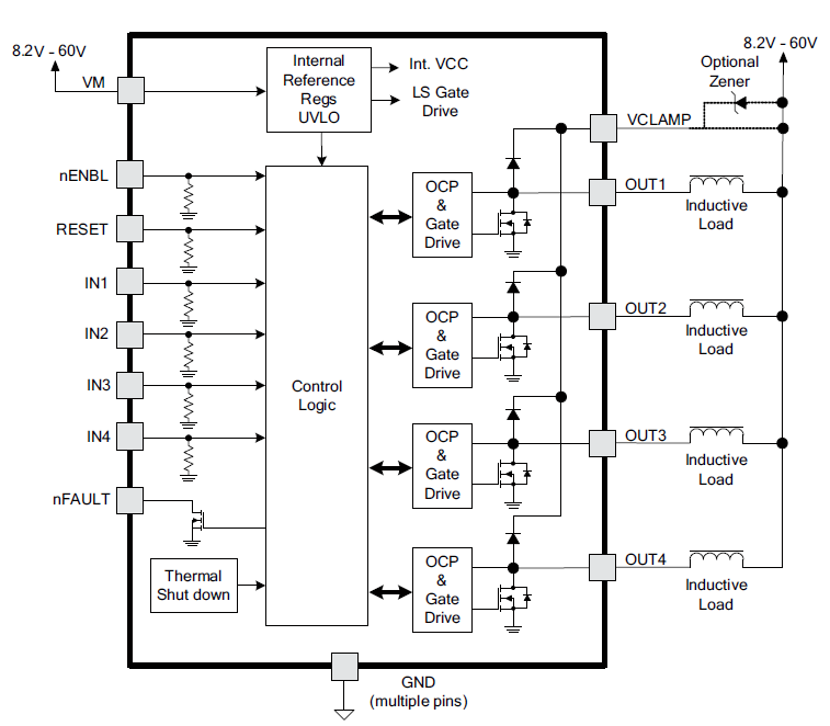
The 8 Channel Driver Arduino UNO Shield is designed to enable users to switch inductive loads for up to 800mA each channel and up to 24V DC with no heat-sink needed. It is ideal for such applications as driving 2x unipolar stepper motors, solenoids, relays, and small DC motors. It uses 2x DRV8803 Chip from Texas instruments which is 4 channel low side driver with over current protection. IC’s Internal shutdown protection function is provided for overcurrent protection, short circuit protection, under-voltage lockout, and over temperature. Faults are indicated by a fault output pin that is normally high and goes low if a fault condition occurs. Reset and enable pins has internal pull-down resistors.
The board can be used to drive mainly inductive loads, since outputs are provided with clamp diode for protection. This shield can drive 2 unipolar stepper motors up to 750mA each with Arduino code. Shield also provides a TSOP1838 IR sensor and pot. IR receiver can help to turn OFF/ON 8 loads using IrR remote, DC motor/stepper motor speed control is possible with the help of onboard trimmer pot.
Features
- Supply 9-24V DC (Supply up to 60V Possible Reade Note) For Load
- Supply Arduino 5V or USB power
- If Load is 12V, Close the Jumper J1, Connect the supply to Arduino DC Jack or CN1
- Load 800mA Each Channel
- Operation LED’s for 8 outputs
- Trimmer Pot for speed control applications
- TSOP1838 IR Receiver for Remote controlled ON/OFF Application
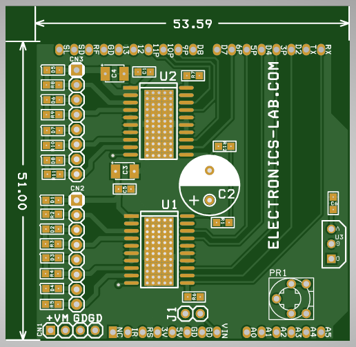
- PCB dimensions 53.39mm x 51.00mm
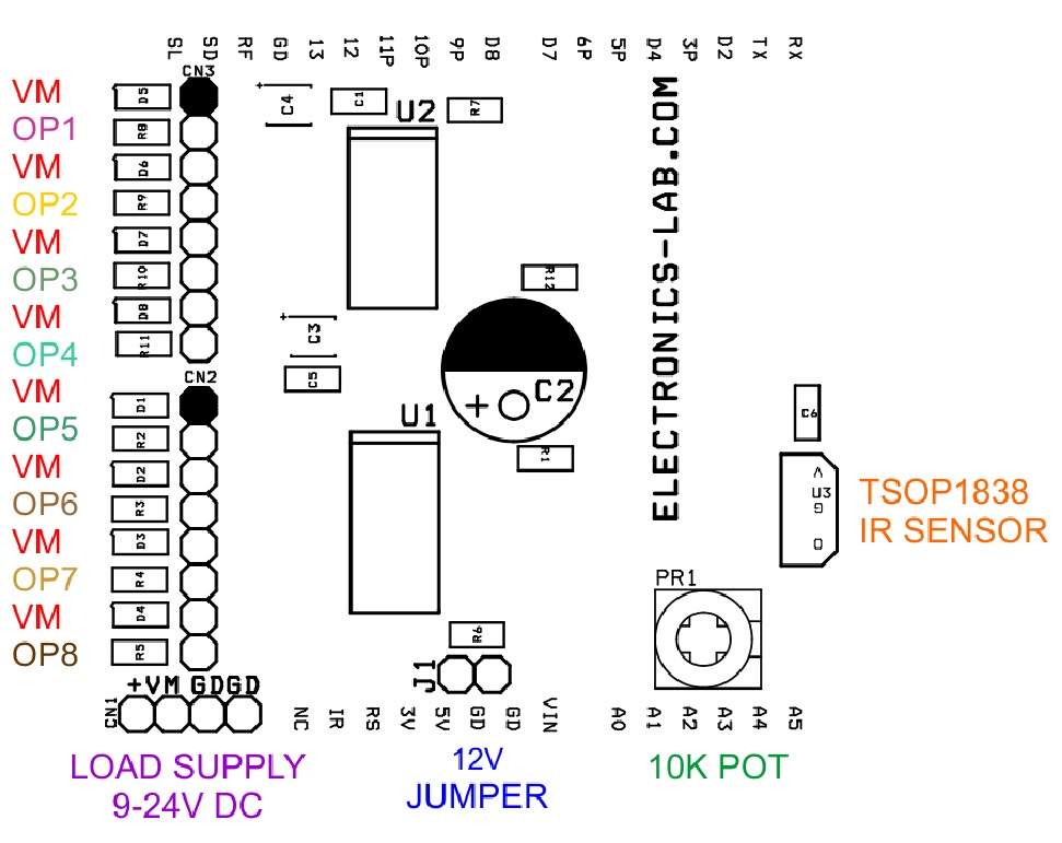
Arduino Pins Configuration (Arduino: DRV8803)
U1: D13>>ENB1 (ENABLE-1), D0>>RST1 (RESET-1), D1>>NF1 (FAULT-1), D5>>IN1, D4>>IN2, D3>>IN3, D2>>IN4
U2: D12>>ENB2 (ENABLE-2), D7>>RST2(RESET-2), D8>>FN2 (FAULT-2), D11>>IN5, D10>>IN6, D9>>IN7, D6>>IN8
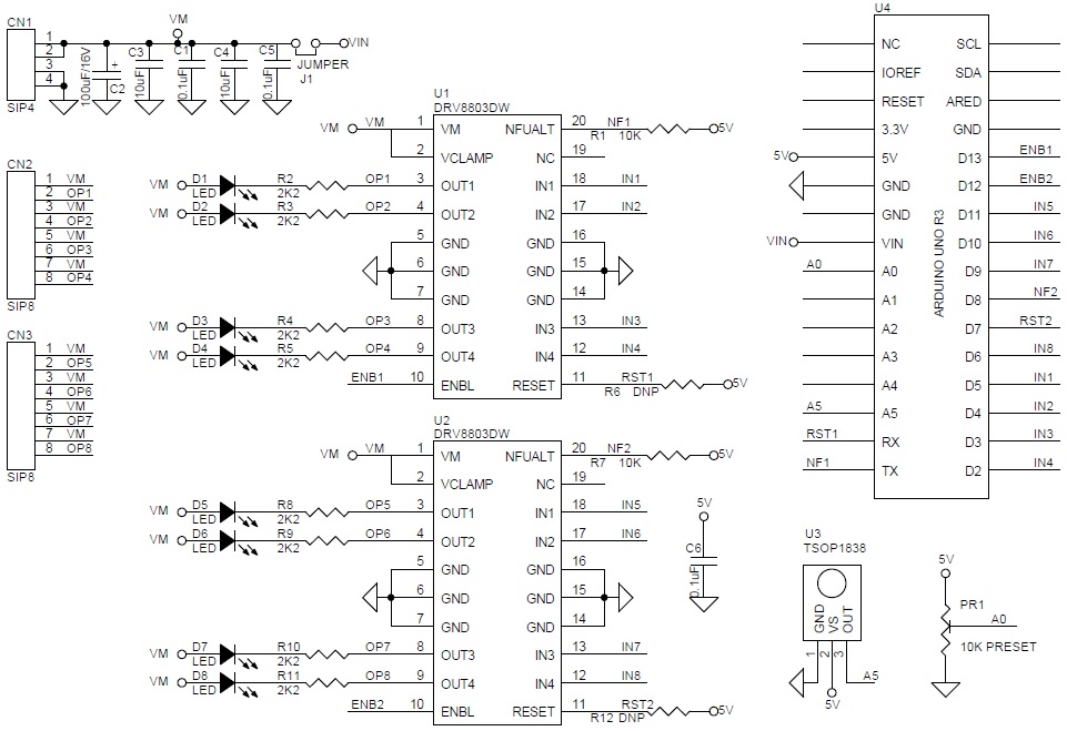
Schematics
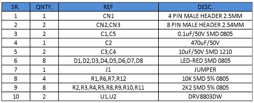
Parts List
Connections
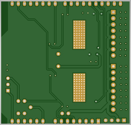
Gerber View
Stepper Motor Example
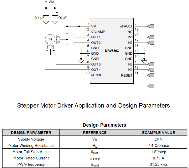
Timing Requirement

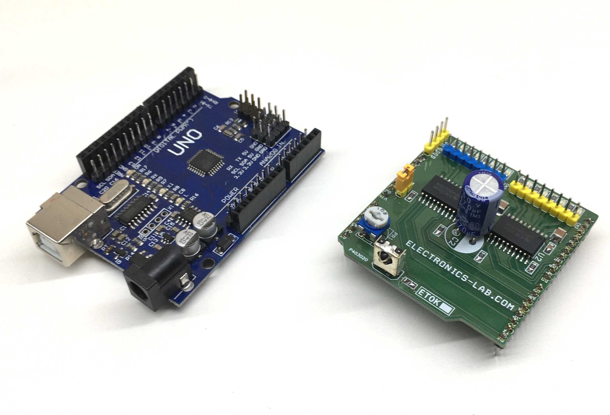
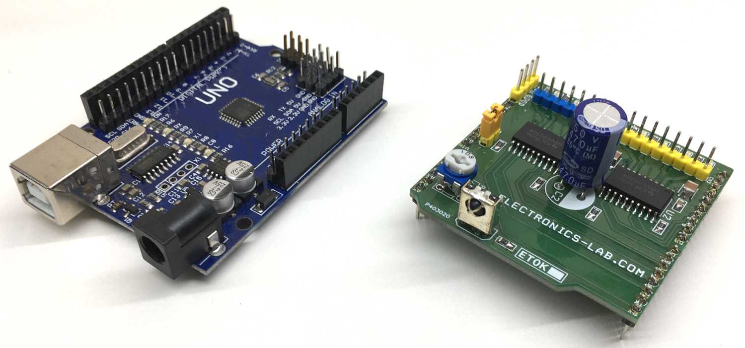
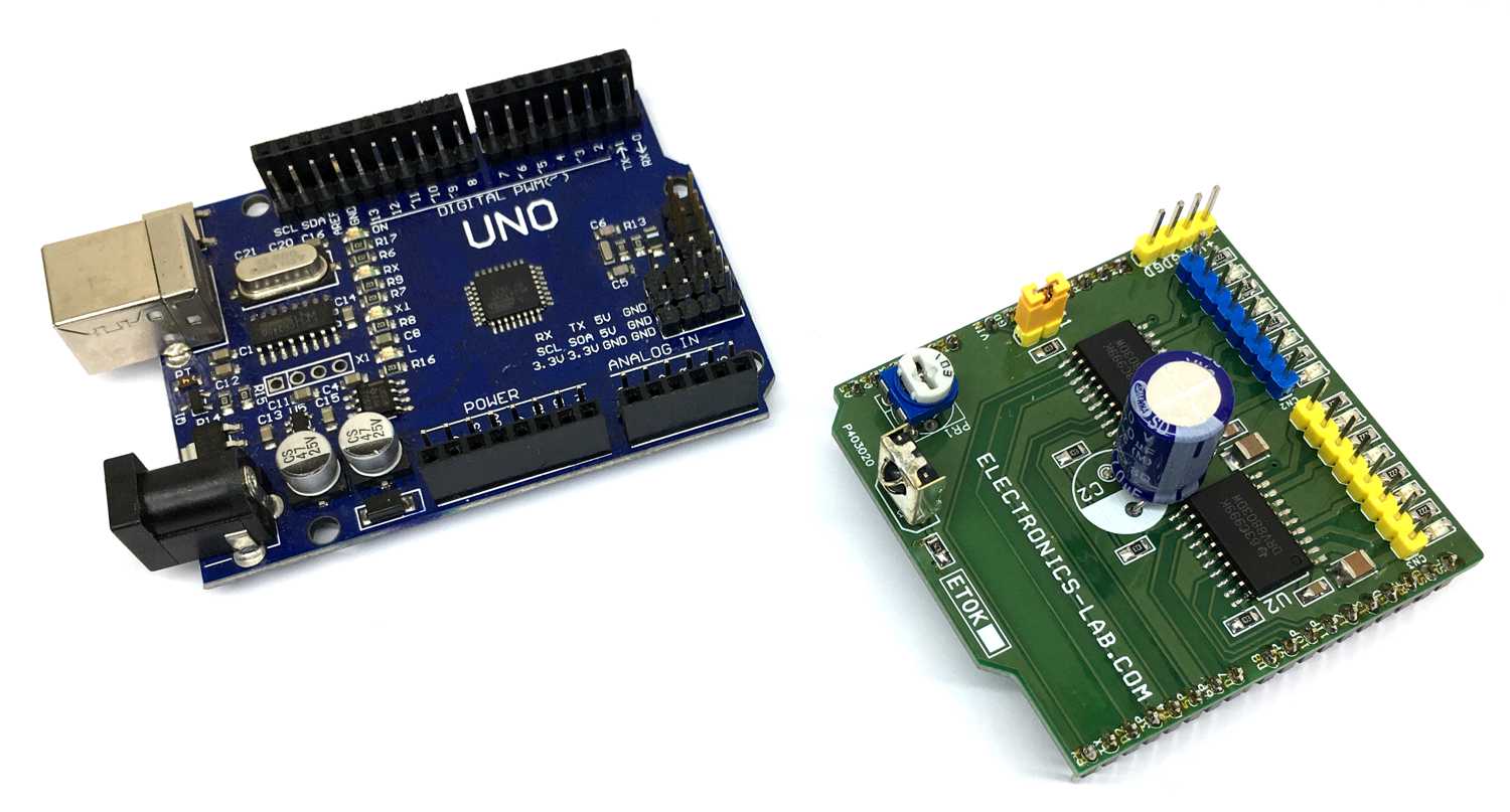
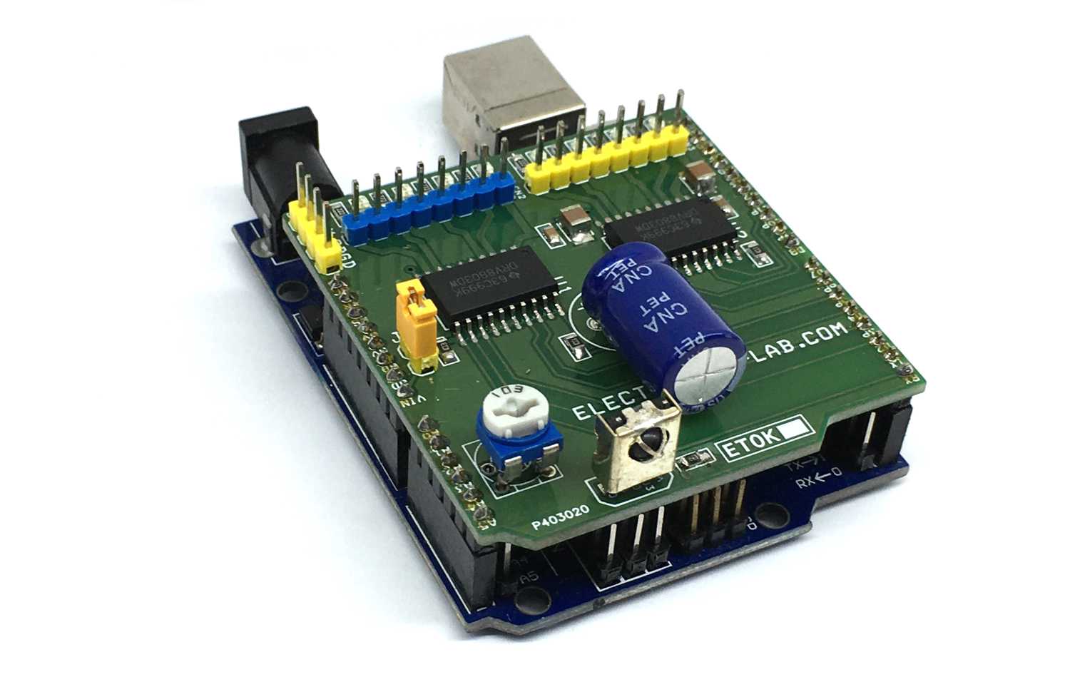
Photos
Video