Two Channel Smart Low-Side Power Switch for Inductive, Resistive and Capacitive Loads – Arduino Shield
The project presented here enables users to switch all kinds of resistive, inductive and capacitive loads, limited by clamping energy (EAS) and maximum current requirement. The user may interface 2 x inductive, resistive, and capacitive loads such as solenoid, dc motor, high current contact switch, high current relay, LEDs, lamps, and piezo etc.
The project presented here enables users to switch all kinds of resistive, inductive and capacitive loads, limited by clamping energy (EAS) and maximum current requirement. The user may interface 2 x inductive, resistive, and capacitive loads such as solenoid, dc motor, high current contact switch, high current relay, LEDs, lamps, and piezo etc. The project is most suitable for inductive loads as well as loads with inrush current. The project has been designed using BTF3050TE IC which is a 50 mΩ single-channel Smart Low-Side Power Switch in a PG-TO252-5 package providing embedded protective functions. The power transistor is built by a N-channel vertical power MOSFET. The device is monolithically integrated. The BTF3050TE is automotive qualified and is optimized for 12V automotive and industrial applications. Two loads can be controlled using Arduino UNO. IC has a thermal-restart function. The device will turn on again, if input is still high, after the measured temperature has dropped below the thermal hysteresis.
In order to optimize electromagnetic emission, the switching speed of the MOSFETs is set to 5 us ON time and 5 us OFF time approx. but this can be adjusted by R6, and R7, refer to the datasheet of the chip for more information. This allows balancing between electromagnetic emissions and power dissipation. Shorting the SRP pin to GND represents the fastest switching speed. Open SRP pin represents the slowest switching speed. It is recommended to put a high ohmic resistor like 200kΩ on this SRP pin to GND. The accuracy of the switching speed adjustment is dependent on the precision of the external resistor used. It’s recommended to use accurate resistors. It is advisable to change capacitor C1 to 470uF if the full load current is in use.
Features
- Operates 2 x Loads (Nominal Load Current Each Channel 3A – 6A both)
- Maximum on State Resistance 100mOhms Each Channel
- Operating Voltage Range 12V-24V for Load ( 3V to 28V Operating Range)
- Operating Supply Voltage Range VCC 3 to 5.5V (Connected to 5V of Arduino Uno)
- Input Signal Maximum 5.5V
- The project can drive Inductive, Resistive, Capacitive Loads
- Arduino Digital pin D3 drives Load-1, and D5 drives Load-2
- BTF3050TE Input PWM < 20Khz or TTL Input (Arduino D3 and D5)
- SW1 and SW2 Resets switch when a Fault condition occurs
- Over-temperature shutdown with auto-restart
- Active clamp over voltage protection of the output
- Enhanced short circuit protection
- Active clamp over voltage protection of the output
- 2 additional LEDs On Arduino D11 and D12 provided for operation indication.
- PCB dimensions: 61.91 x 50.64 mm
Testing the board
Arduino Example Code Provided to test the board at the end of the article.
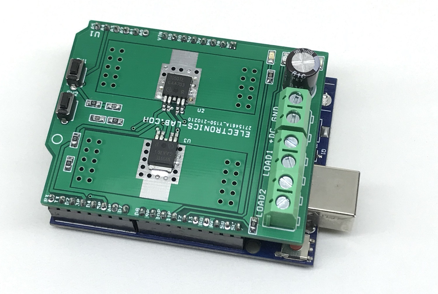
Connect the load at Z1 (Load1) and Z2 connector, Connect the load power supply at CN1, Upload the Arduino code to Arduino UNO, mount the shield on Arduino Uno. Each load will be ON for 1 Second sequentially, at the same time LED D2 and D3 will indicate the operation ON/OFF. Code is determined with ON/OFF operation of loads. Users can write their own code to use PWM and Fault functions.
BTF3050TE Details
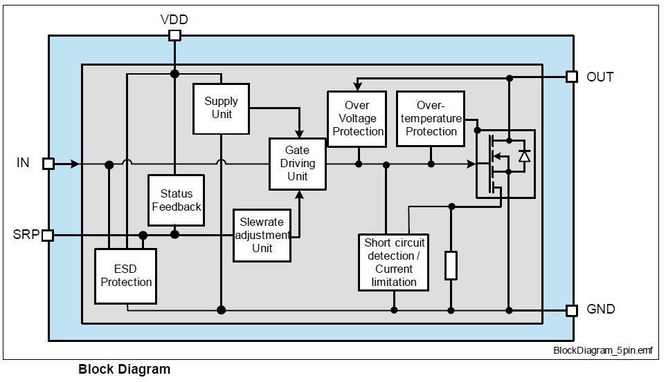
Over Voltage and Over Temperature Protection
The over-voltage protection gets activated during inductive turn-off conditions or other overvoltage events (e.g. load dump). The power MOSFET is limiting the drain-source voltage if it rises above the VOUT(CLAMP). The over-temperature protection prevents the device from overheating due to overload and/or bad cooling conditions. The BTF3 has a thermal-restart function. The device will turn on again if the input is still high after the measured temperature has dropped below the thermal hysteresis.
Slew Rate in Fault mode (fault signal set)
Besides the normal slew rate function, the SRP pin is also used as fault feedback output. In case of a latched fault caused by over-temperature detection, the SRP pin will be internally pulled to VCC. For details. In this operation mode (latched fault signal) the slew rate control by RSRP will be ignored and the switching speed (dynamic characteristics) will be set to fault mode default values. As long as the fault signal is set and the SRP-pin is not shorted to GND a fast default slew rate adjustment (like for RSRP R6, R7= 6.2kΩ) will be applied to the device.
Normal operation mode (slew rate mode; low signal)
The pin is used to define the switching speed of the BTF3050TE. A resistor to ground defines the strength of the gate driver stage used to switch the power DMOS. The SRP pin works as a controlled low voltage output with a normal voltage up to VSRP(NOR), driving from VCC a current out of the SRP-pin through the slew rate adjustment resistor. The voltage on the SRP pin in normal operation mode is VSRP(NOR), signaling a low signal to the microcontroller.
Latched Feedback mode (internal pull-up to VCC; high signal)
The pin is used to give alarming feedback to the Arduino after an over-temperature shutdown. The SRP pin is pulled to Vcc by an active internal pull-up source providing typical a current ISRP(FAULT), intended to signal a logic high to the Arduino. This mode stays active independently from the input pin state or internal restarts until it will be reset. During this mode, the slew rate of the device is set to a fast “fault” mode slew rate (similar to the switching times at RSRP = 6.2kΩ.) The latched fault/feedback mode and the signal are available at slew rate resistors of 5kΩ < RSRP < 70kΩ.
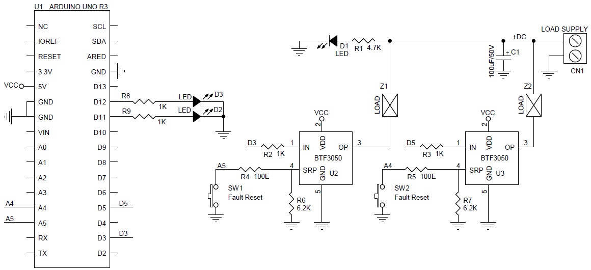
Schematic
Parts List
| NO. | QNTY. | REF. | DESC. | MANUFACTURER | SUPPLIER | SUPPLIER PART NO |
|---|---|---|---|---|---|---|
| 1 | 1 | CN1 | 2 PIN SCREW TERMINAL 5.08MM PITCH | PHOENIX CONTACT | DIGIKEY | 277-1247-ND |
| 2 | 1 | C1 | 100uF/50V ELECTROLYTIC | PANASONIC | DIGIKEY | P10397TB-ND |
| 3 | 3 | D1,D2,D3 | LED SIZE 0805 | OSRAM | DIGIKEY | 475-1410-2-ND |
| 4 | 1 | R1 | 4.7K 5% SMD SIZE 0805 | MURATA/YAGEO | ||
| 5 | 4 | R2,R3,R8,R9 | 1K 5% SMD SIZE 0805 | MURATA/YAGEO | ||
| 6 | 2 | R4,R5 | 100E 5% SMD SIZE 0805 | MURATA/YAGEO | ||
| 7 | 2 | R6,R7 | 6.2K 1% SMD SIZE 0805 | MURATA/YAGEO | ||
| 8 | 2 | SW1,SW2 | TACTILE SWITCH | E-SWITCH | DIGIKEY | EG2513-ND |
| 9 | 2 | U1 | ARDUINO UNO R3/SHIELD | ARDUINO MALE HEADER 2.54MM PITCH | DIGIKEY | S1011EC-40-ND |
| 10 | 2 | U2,U3 | BTF3050 | INFINION | DIGIKEY | 2156-BTF3050TEBATMA1-ND |
| 11 | 2 | Z1,Z2 | 2 PIN SCREW TERMINAL 5.08MM PITCH | PHOENIX CONTACT | DIGIKEY | 277-1247-ND |
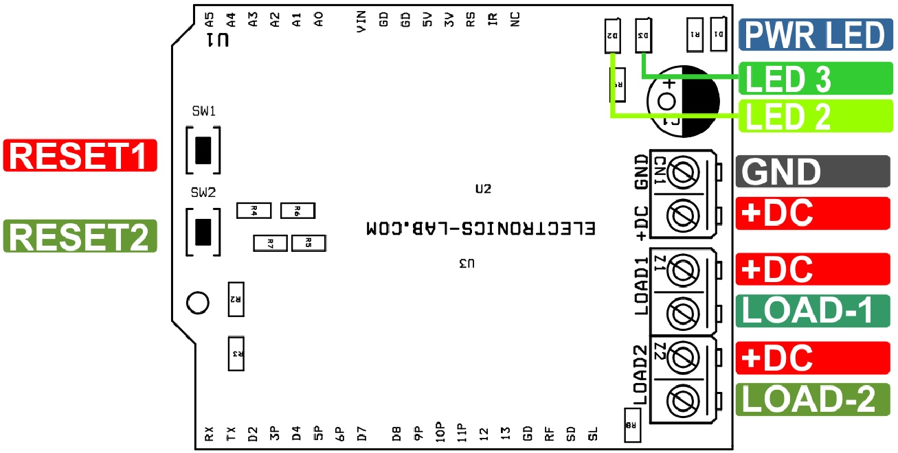
Connections
Gerber View
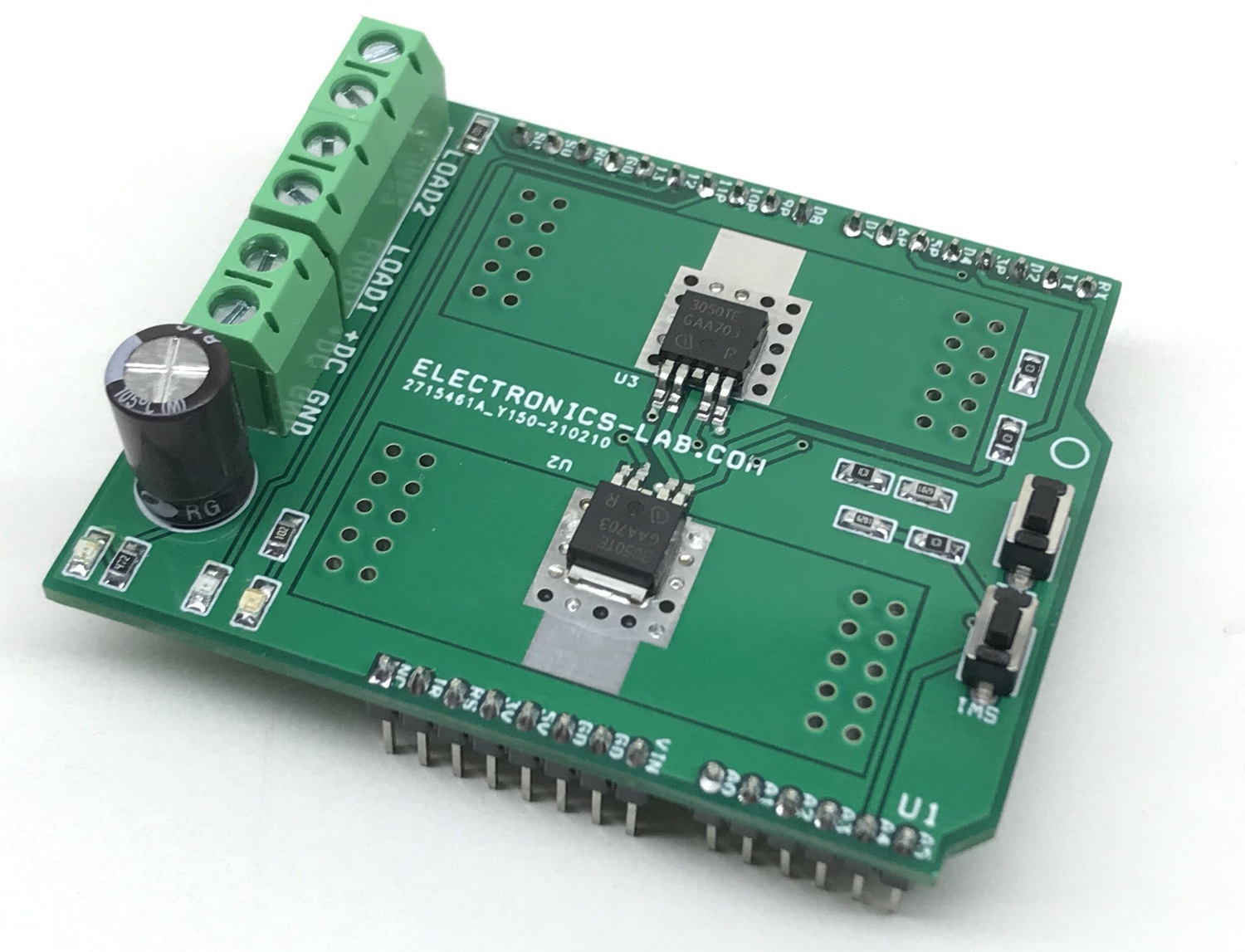
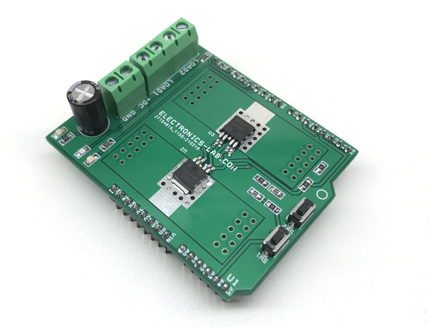
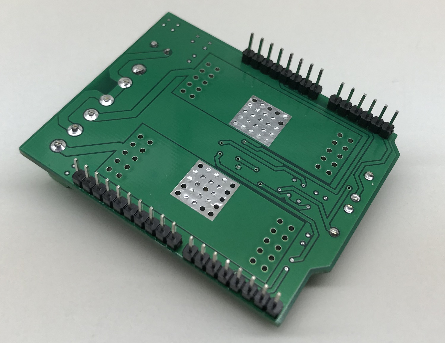
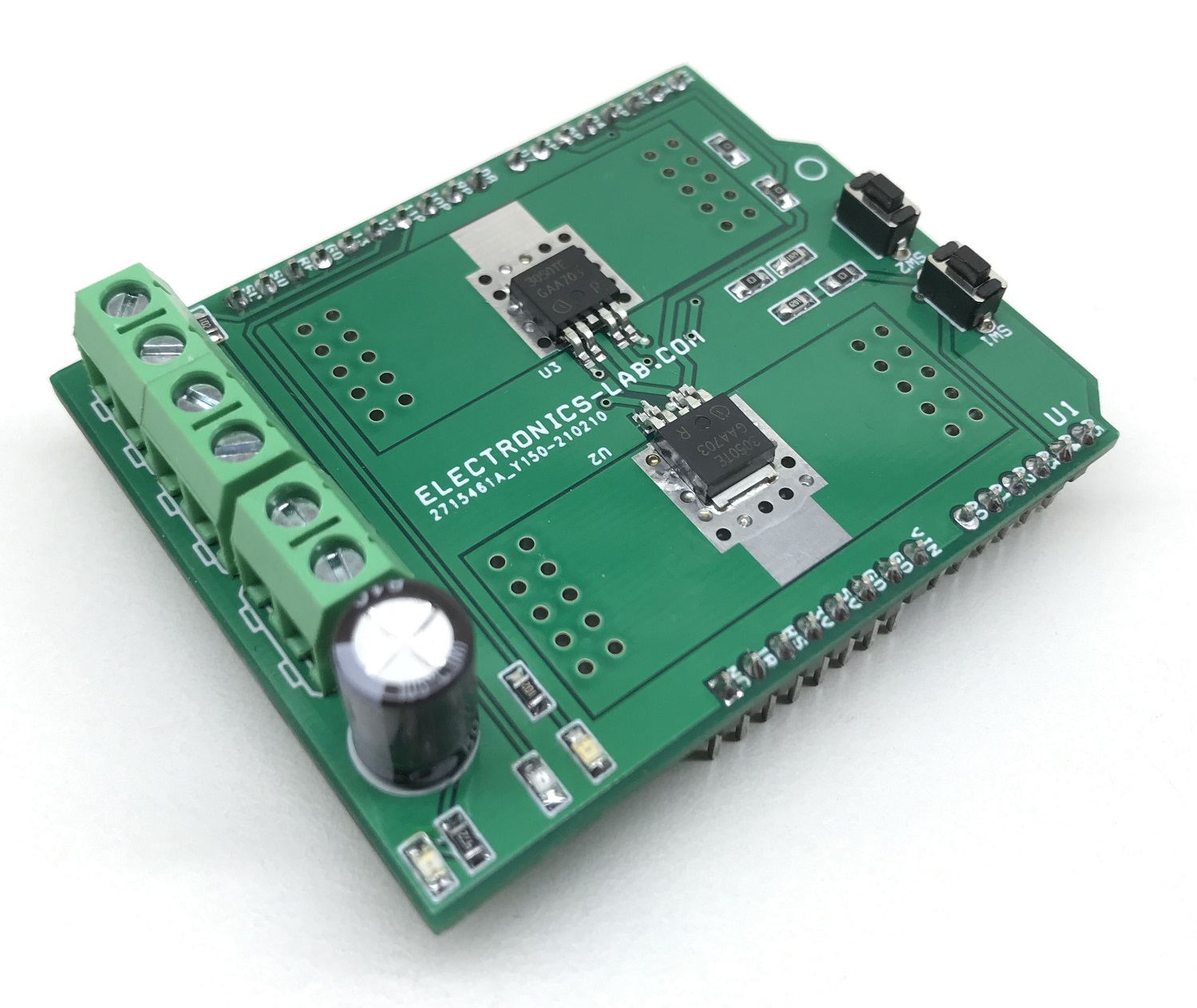
Photos
Video