AC Resistance and Impedance
Introduction The electric resistance is a property that characterizes how a particular component creates an opposition to the flow of current when a voltage difference is applied to its terminals. In this tutorial, we will focus on the opposition that a resistor generates when an AC voltage is applied to it.
Introduction
The electric resistance is a property that characterizes how a particular component creates an opposition to the flow of current when a voltage difference is applied to its terminals. In this tutorial, we will focus on the opposition that a resistor generates when an AC voltage is applied to it.
In the very first section, in order to get further than the Ohm’s law, a simple presentation gives some details about the concept of resistance and the resistor components. We will see in the second section the behavior similarities between the resistance in AC regime and in DC regime.
The following sections will highlight two phenomena that induce differences between the AC and DC resistance of resistors, specially when the frequency increases.
Presentation : the resistivity
In this section, we define a little more clearly what the resistance is and on what it depends on. As the title suggests it, the primary concept is called the resistivity. Let’s consider a parallelepipedic material of cross section A and length L with two terminals such as presented in Figure 1 :
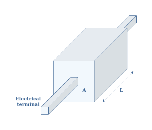
The resistivity ρ is expressed in Ω.m and it is an intrinsic property of the material. This means that the resistivity does not depend on the geometry. The resistivity value of any material can simply be found in online tables or in books.
Moreover, resistivity is one of the rare physical quantity that varies across so many orders of magnitude. For example, copper is one of the less resistive materials, its resistivity is ρcopper=1.7×10⁻⁸ Ω.m. On the other hand, Teflon is one of the most resistive materials with a resistivity of ρTeflon>1023 Ω.m.
For a specific geometry, such as in Figure 1, the resistivity and resistance R are linked by the following formula given in Equation 1 :
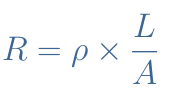
We can understand with this formula that the resistance if affected by the geometry and the intrinsic resistivity of the material :
- If the length increases, the electrons have to go through more resistive material, thus the resistance increases.
- If the cross section decreases, less possible path are available for the electrons (like for a simple road or a 4 lane highway), thus the resistance increases.
- If the resistivity increases, the material is intrinsically more resistive, therefore the resistance increases again.
Resistors are usually made of ceramic or carbon powder, the resistivity is ρcarbon≅ 10-3 Ω.m. For example, if we choose a ratio L/A=1000, we get a resistance of a few Ohms.
Similarities in AC regime
In DC regime, the resistance generated by a resistor is extremely simple to describe, it is described by Ohm’s law. It is a linear relationship between the voltage V and current I where these two quantities are linked by a factor R called the resistance such as U=R×I.
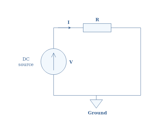
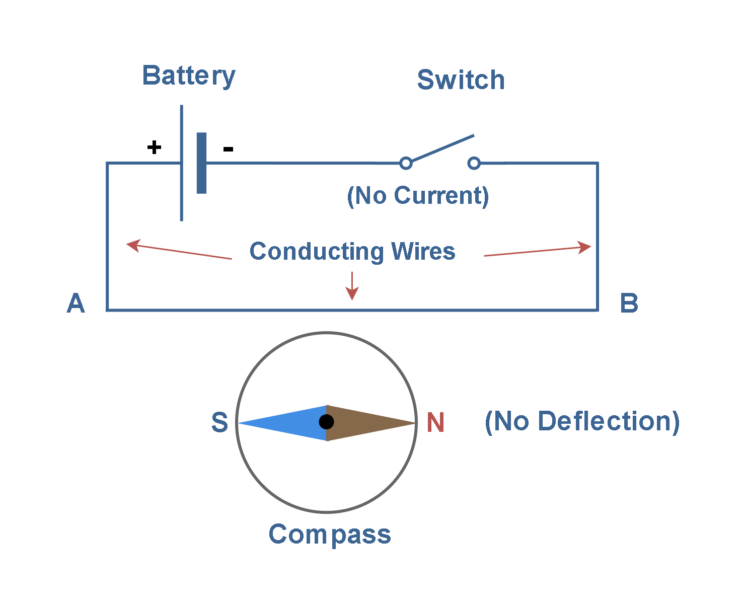
So what happens if we replace the DC source by an AC source in Figure 2 ? Will Ohm’s law still be possible to apply ?
The answer is simple, under normal conditions of frequency and amplitude (not too high), the resistor behaves strictly the same than in DC regime. The complex impedance of the resistance is therefore a real number Z=R+j×0=U/I.
In DC regime, the power generated by heating is given by the product of voltage and current : P=U×I. This is also true in AC regime for the instantaneous power : P(t)=U(t)×I(t). However, the average power Pavg dissipated by Joule’s heating is more interesting to focus on. The formula for Pavg is given below in Equation 2 where Φ states for the phase shift between the voltage and current:

Since the impedance of a resistor is real, we can refer to the tutorial about complex numbers to understand that the phase shift Φ is equal to zero. The subscripts “RMS” states for Root Mean Square, its definition is fully explained in the AC waveform tutorial.
For the particular case of a purely resistive circuit, the expression of the average power reduces therefore to Pavg=URMS×IRMS.
Disparities in AC regime
We pinpoint in this last section two effects that modify the AC resistance compared to the DC resistance when the frequency of the AC source increases a lot. The section is divided in two subsections to treat these phenomena independently.
The skin effect
Before talking about this phenomenon, we need to understand its origin. This first effect is due to the law of electromagnetic induction that we have mentioned in the AC waveform tutorial.
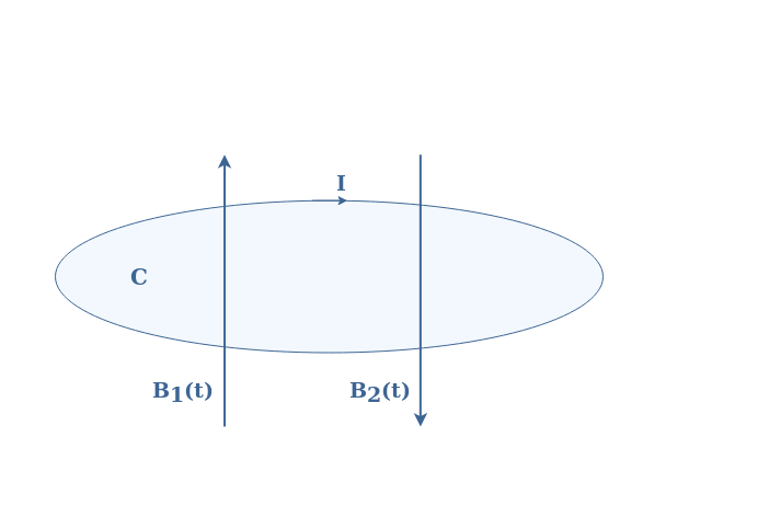
The induction law or Lenz’s law states that considering a closed electric circuit C in which a variable magnetic field B1(t) penetrates, a current I is generated in order to create an opposite magnetic field B2(t) to moderate the variation of B1(t).
This electromagnetic effect is widely present in many technologies and can be used in different ways, it is how inductor, turbines, transformers or induction cookers work.
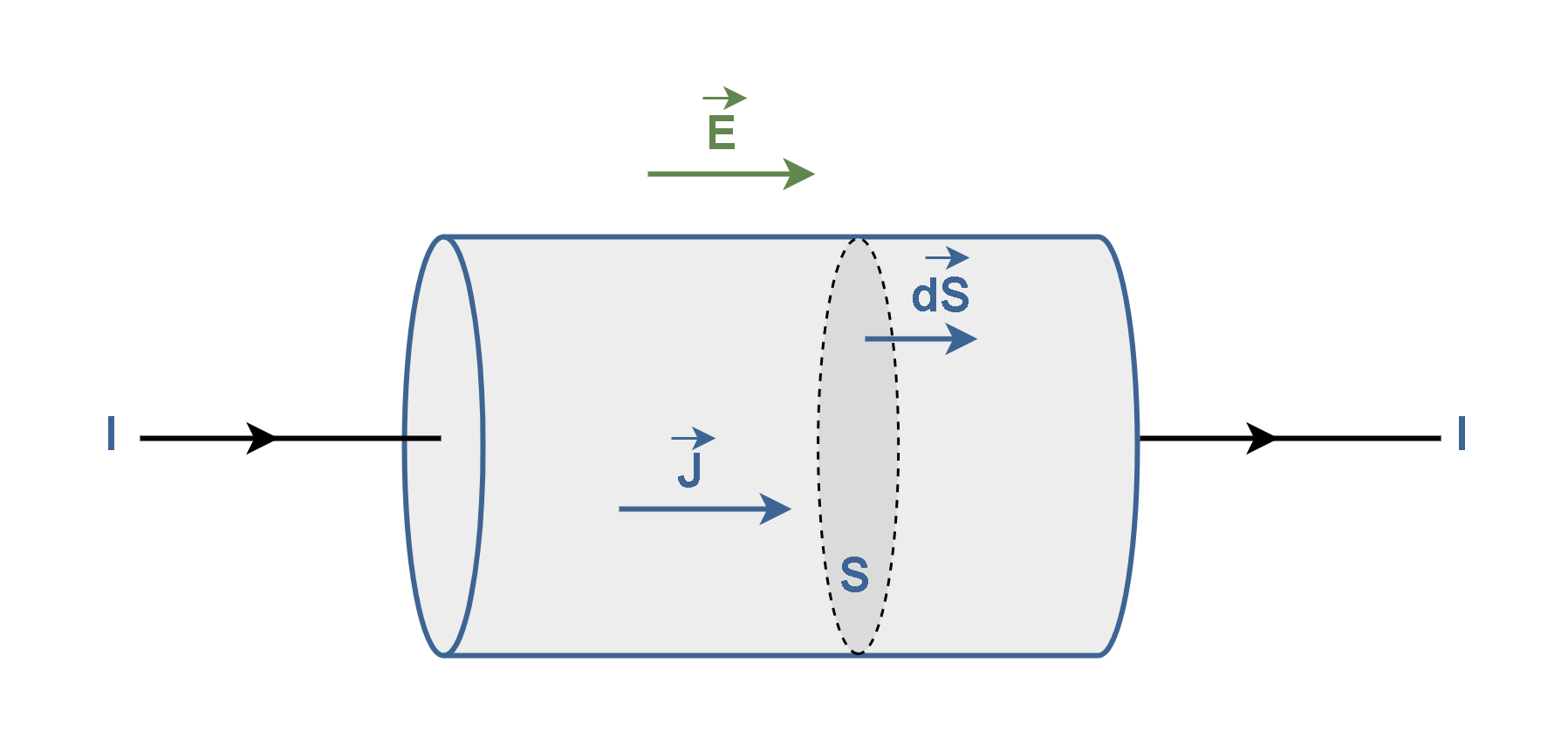
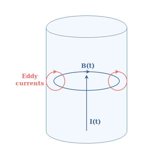
Let’s be back now to a piece of resistive material such as already presented in Figure 1. In the same way that an alternating magnetic field generates current loops, an alternating current I(t) generates magnetic loops B(t) as well. Since magnetic loops are generated within the resistive material, it creates such as shown in Figure 3 current loops. These current loops have a particular name : they are called Eddy currents or Foucault currents.
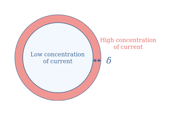
Such currents are concentrated at the border of the resistive material such as presented in Figure 4 above. This phenomenon called skin effect tends to become more important when the frequency of the alternating current I(t) increases.
The most important parameter describing the skin effect is called the skin depth and noted δ. It denotes the thickness from the border of the resistive material where most of the Eddy currents are concentrated.
This value is proportional to 1/√f where f is the frequency. Therefore increasing the frequency tends to decrease the skin depth. When the frequency of the alternating current becomes very high, most of the current is located in a small region near the resistive material border such as depicted in Figure 5 :
The effective cross section A of the material becomes then smaller and therefore, according to Equation 1, the resistance increases.
For a certain value of the frequency, which depends on the material, the skin effect tends to increase the AC resistance compared to the DC resistance : RAC>RDC.
The proximity effect
Electromagnetic induction is also the cause of another effect known as proximity effect that can greatly affect the AC resistance of a circuit. The proximity effect is observed when two or more nearby conductors are carrying current.
Let’s consider for the simplicity of the example two parallel wires W1 and W2 carrying the same AC current I(t). If the frequency of the current is high enough, a magnetic loop B(t) will be generated by W1 (also by W2 but not represented in Figure 6) around itself. If the wires are close enough, the magnetic loop will cross the second wire and generate, as explained previously, Eddy currents in W2 :
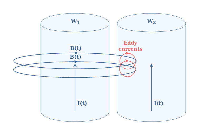
Since the effect is symmetrical, W2 also induces Eddy currents in W1. The current concentration profile would look, for this example, as illustrated in Figure 7 below :
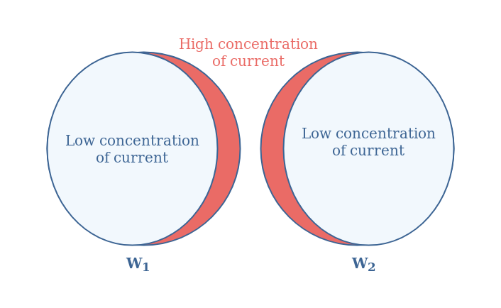
Such as for the skin effect, the proximity effect is the result of a modification of the distribution of current within the resistive materials that tends to increase the resistance by decreasing the effective cross section. This effect is also enhanced when the frequency increases and can lead up to one or more orders of magnitude of difference between the AC and DC resistances.
Conclusion
This tutorial has been focusing on the similarities and disparities between the value of the resistance of a resistive material in DC and AC regime.
First of all, we have presented what exactly the resistance consists of by presenting the concept of resistivity. We have seen that the resistance depends on this intrinsic property and on the geometry of the material considered.
In a second section, we investigate the AC resistance under normal operating condition (not too high frequency). Ohm’s law can be applied in AC regime such as in DC regime. Moreover, since no phase shift is observed, the expression of the power is similar than in DC regime by using the RMS values for the voltage and current quantities.
In the last section, two phenomena pinpoint the fact that when the frequency increases, the AC resistance can get much higher than the DC resistance.
The first effect is called the skin effect and is due to a redistribution of the current near the border of the conductor. This decreases the effective cross section where the current passes, which increases the resistance.
The second effect is the proximity effect and happens when two nearby conductors are simultaneously carrying an alternating current, sufficiently high enough in frequency. It leads as well to a redistribution of the current within both conductors near one of their border which, similarly than the skin effect, increases the resistance of the wires.
However, these effects only start to greatly affect the circuit when the frequency is very high. For example, at 50 Hz, cooper wires do not need to be wider than 8 mm in radius since the skin depth at this frequency is around 9 mm. At 10 MHz, this depth becomes around 21 μm, which is still not a problem of design for Printed Circuit Boards (PCB) that can go down to width of 10 μm. We can say that above 100 MHz, the skin and proximity effects related to that depth become constraining to properly design circuits.