Phase difference and Phase shift
Introduction When we are listening to a song, we perceive the sinusoidal sound waveforms as music. Their amplitude gives us how loud the signal is and the frequency tells us if the sound is low or high pitched.
Introduction
When we are listening to a song, we perceive the sinusoidal sound waveforms as music. Their amplitude gives us how loud the signal is and the frequency tells us if the sound is low or high pitched. However, the third important parameter, which is the phase, is harder to experience by ears.
This tutorial will clarify and give more details about the phase parameter that we already explored in one of our previous tutorials about Phase Splitters. The first section will, therefore, give a presentation of the concepts of phase and phase difference as a reminder.
In the second section, we detail more aspects of the concept of phase shift and we focus on a particular case when the signals are not synchronized.
The third and last section will finally present the important role of the phase difference in the interference phenomenon.
Presentation
The phase of a sine signal is often noted with Φ and measured in radians (rad) or degrees (°) and can vary between -π and +π rad or -180° and +180°.
On a graph, the phase of an AC signal represents the initial state of its related sine function at the origin of time :
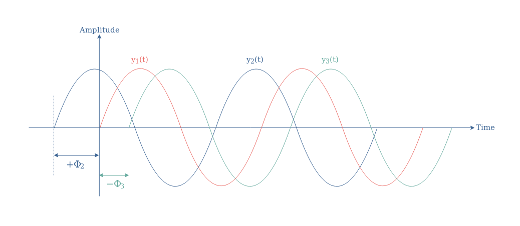
The phase Φ of a signal can be of three different nature and dictates the position of the waveform around the vertical axis :
- Equal to 0 (° or rad) such as for the signal y1(t) which act as a reference signal
- Be positive such as for the signal y2(t)
- Be negative such as for the signal y3(t)
The phase of a single signal is not very relevant because whether the AC waveform is of electrical or mechanical nature, the perception will remain unchanged if the signal has a phase or not. What is more important and can clearly be perceived is a phase difference, also called a phase shift between two signals of the same frequency.
Phase difference
Between signals of the same frequency
What is important to keep in mind during this section is that we only talk about a phase shift between two signals with identical frequency. Consider therefore two signals of the same frequency with different phases and possibly different amplitudes: y1(t)=Asin(ωt+Φ1) and y2(t)=Bsin(ωt+Φ2). We define the phase difference as the quantity ΔΦ21=Φ2-Φ1.
In Figure 1, we have ΔΦ21=+Φ2, ΔΦ31=-Φ3, and ΔΦ32=-Φ3-Φ2. A positive phase difference, such as ΔΦ21, indicates that the signal y2(t) temporarily precedes the reference signal y1(t), we also say that y2(t) leads y1(t). A negative phase difference, such as ΔΦ31 and ΔΦ32, indicates that the signal y3(t) follows the signals y1(t) and y2(t), we also say that y3(t) lags y1(t) and y2(t).
Among all of the values between -180° and +180° or -π and +π rad that a phase difference can take, a few ones can be highlighted and illustrated in the following Figure 2 :
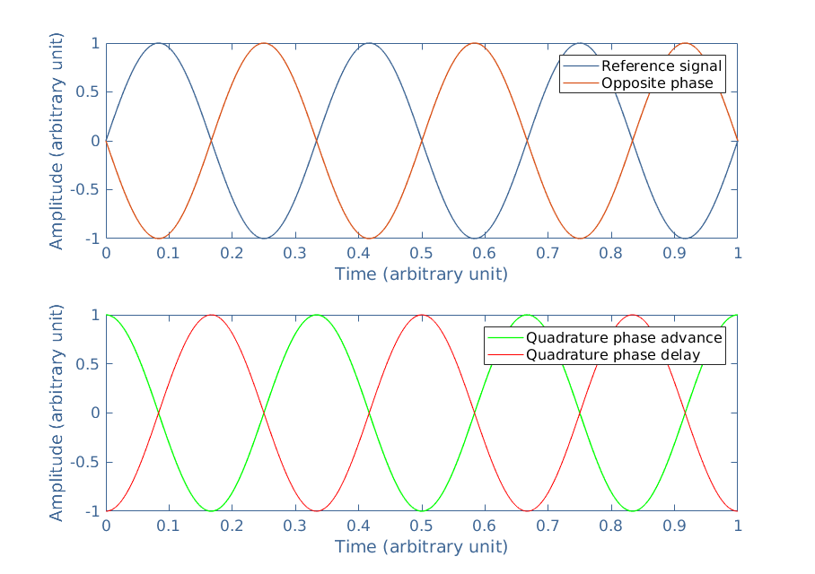
An opposite phase is characterized by a phase shift of +180° or +π rad, which is strictly identical to -180° or -π rad. If the reference signal is Vref=vrefsin(ωt), then the opposite signal is Vopp=vrefsin(ωt+π)=-vrefsin(ωt), therefore, Vref+Vopp=0.
Quadrature signals are characterized by a phase shift of +90° or +π /2 rad for the “advance” and -90° or -π /2 rad for the “delay”.
Between the current and voltage signals
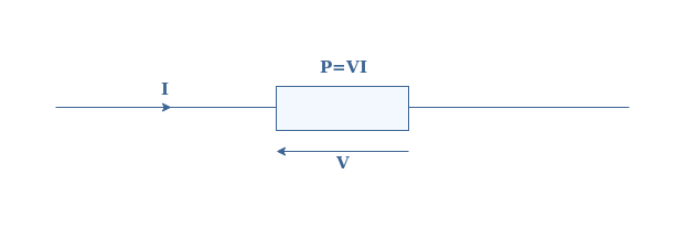
In this subsection, we focus specifically on the phase shift of the current (I) and voltage (V) signals across an electrical dipole and investigate its consequences regarding power.
In the DC regime, the dissipated power (P) across a dipole is given by the product of the voltage and current :
In the AC regime, this representation is no longer true since both the voltage and current are alternating. Consider the voltage across the dipole to be V=Vrms√2.sin(ωt) and the current of the same frequency presenting a phase difference of +ΔΦ: I=Irms√2.sin(ωt+Φ). With Vrms and Irms being the root mean square values.
It can be shown that the active power dissipated in the dipole in AC regime is given by Equation 1:
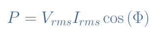
The term cos(Φ) is known as the power factor and gives the efficiency of a receptor to absorb the power of a source. This factor is a real number between 0 and 1 and these two extrema reflect very different behavior :
- If cos(Φ)=1 the dipole is considered purely resistive, the phase shift between the voltage and current is zero. The dipole does not present any inductive or capacitive behavior.
- If cos(Φ)=0 the dipole is purely reactive, the phase shift between the voltage and current is maximum, equal to ±90° or ±π/2 rad. In this case, the dipole does not consume any power but instead returns it to the circuit.
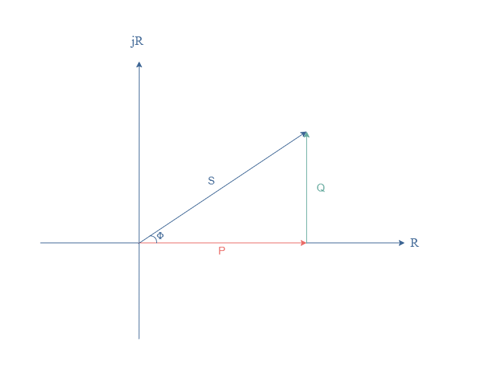
The power given in Equation 1 is called the active power (P), the product Vrms×Irms is known as the apparent power and noted S. It is the power that would be dissipated if the component was purely resistive. The quantity Vrms×Irms×sin(Φ) is the reactive power and noted Q. These quantities can be linked thanks to the phase shift ΔΦ in the same complex power diagram :
Between signals of similar frequency
In this section, we consider two signals y1(t) which is the reference and y2(t) phase-shifted of Φ of similar frequencies but not strictly identical: ω1≠ω2. Usually, a phase-shift can only be defined for two signals of the same frequency, but in this particular case, it still makes sense to define a phase-difference as the frequencies are similar. If the frequencies are too different, usually when ω1>2ω2 for example, it does not make sense to define it since the phase difference varies as much as the signal itself.
In the case where the signals are of similar frequency, the phase difference is not constant anymore but slowly varies with time: ΔΦ(t)=(ω2-ω1)t+Φ.
The superposition of these two signals is interesting because of the creation of a beating phenomenon such as illustrated in Figure 4:
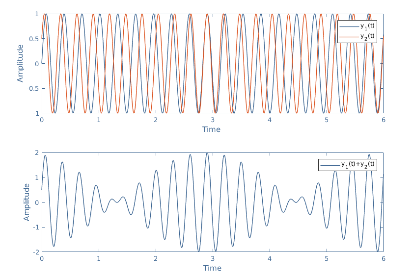
The beating takes his name from the acoustic domain where this phenomenon is particularly audible and easy to experience, however, it also appears in optics, electronics, mechanics etc… The beating is actually a particular case of interference, which we focus on in the next section.
Interference
We can see in Figure 4 that a superposition of sine waveforms results sometimes in addition to the amplitudes when the signals are in phase or in a subtraction when the signals are in opposition of phase. This phenomenon is known as interference and takes place when the signals are of the same frequency.
Consider again two sinusoidal waveforms of identical frequency : y1(t)=A1sin(ωt+Φ1) and y2(t)=A2sin(ωt+Φ2). Let’s call y3(t) the superposition y1(t)+y2(t) and A3 its amplitude. It can be shown that the amplitude of y3(t) satisfies the following equation :
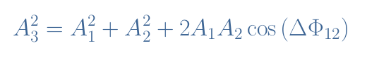
We can notice that the phase difference between y1(t) and y2(t) plays an important role in the final amplitude of the resulting signal. Two cases are interesting to highlight :
- ΔΦ12=0, the signals are in phase and the amplitude A3 is maximal as satisfies A32=(A1+A2)2. In this case, we say that the interference between y1 and y2 is constructive.
- ΔΦ12=±π rad, the signals are in opposition of phase and the amplitude A3 is minimal and satisfies A32=(A1-A2)2. In this case, the interference between y1 and y2 is destructive.
When the phase difference is between these two extrema, we can plot a graph showing the evolution of A3 as a function of ΔΦ12 :
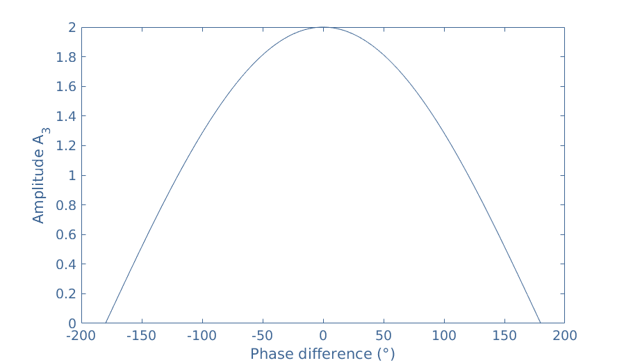
In this figure, we choose for the sake of simplicity A1=A2. We can see again that when ΔΦ12=0, A3=A1+A2=2 and when ΔΦ12=±180°, A3=A1-A2=0.
Conclusion
This tutorial has given a detailed presentation about the concept of phase and phase difference, moreover, it has pinpointed its importance through some examples.
First of all, we present what is the phase of a signal and in which unit it is measured. The concept of phase alone, however, is not very relevant and this is why we focus on the following sections about the phase difference or phase shift.
In the first paragraph of the second section, we define the phase shift ΔΦ and give some vocabulary related to particular cases of phase difference: in-phase (ΔΦ=0°), the opposition of phase (ΔΦ=±180°) and the quadratures (ΔΦ=±90°).
In a second subsection, we highlight the importance of the phase-shift between the current and voltage in a circuit. The power dissipated in any electronic component is directly proportional to the cosine of the phase shift, which is called the power factor.
In the last section, we link and explain the interference phenomenon to the phase shift parameter. The beating phenomenon which is explained previously in the article is a particular case of interference.