Phasor Diagrams and Phasor Algebra
Introduction AC electric signals can be represented by three different methods in order to characterize and realize algebra operations with them. Already two methods have been presented in previous tutorials and a new graphical one is introduced later in this tutorial.
Introduction
AC electric signals can be represented by three different methods in order to characterize and realize algebra operations with them. Already two methods have been presented in previous tutorials and a new graphical one is introduced later in this tutorial.
The most simple and natural way is to write an AC signal y(t) as a sine function of time such as explained in the tutorial of Sinusoidal Waveforms :
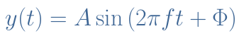
With A being the amplitude, 2πf=ω being the angular velocity and f the frequency, Φ being the instant phase.
However, this representation is not convenient to realize algebra of two or more AC signals of the same frequency because there is no general trigonometric formula Asin(X)+Bsin(Y) to write a result under the form shown in Equation 1.
In the Complex Numbers tutorial, we have seen that y(t) can be rewritten as a complex number. This second way of writing a sine waveform simplifies the algebra between AC signals.
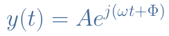
Indeed, let’s consider for example that we want to add two signals y1(t) and y2(t), with their respective parameters A1, A2, Φ1, Φ2 and ω1=ω2. Using the complex form, the term ejωt can be put as a common factor :

With A3 and Φ3 depending on A1, A2, Φ1, Φ2 being the new parameters amplitude and instant phase of the resulting signal y3(t).
In this tutorial, we will introduce a new representation of sine waveforms which is graphical and it is known as the phasor representation. The first section will present this new concept and clarify where it comes from.
At the core of the article, we will focus on the phasor’s algebra: how to realize additions/subtractions and differentiations/integrations. It will be highlighted why this representation makes the algebra of AC signals more convenient.
Presentation
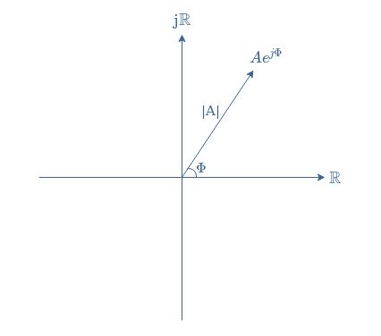
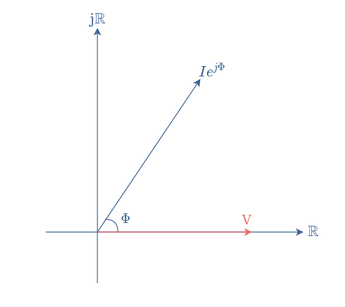
The idea of a phasor comes from the complex representation of AC signals. From Equation 2, we can indeed split the exponential term in two parts : Ae(jωt+Φ)=AejωtejΦ. We call phasor the quantity AejΦ, which is a complex number and can, therefore, be represented in the complex plane as a vector where Φ is the angle between the real numbers axis and phasor and A is the module of the vector :
Sometimes, AejωtejΦ can refer to the phasor, in this case, the vector rotates anticlockwise at an angular velocity of ω.
There is no real point in representing a single signal as a phasor, however, phasor diagrams become appreciated to solve some problems with two or more AC signals in an easier way than with algebra as we will present in the next section.
A phasor diagram consists of the same figure as presented above but with two or more vectors. Consider for example an AC signal which voltage and current are phase-shifted of Φ: V(t)=Vsin(ωt); I(t)=Isin(ωt+Φ). In this case, we represent V(t) as a reference phasor aligned with the real number axis and I(t) with an angle Φ oriented in the anticlockwise direction :
In this particular case, the current is leading the voltage or we can also say that the voltage is lagging the current. More information about this fact can be found in the tutorial of Phase Splitter.
We note that since phasors represent the state of a signal at a particular period of time, an infinity of a diagram is available if we take t≠0. For this reason, the following diagram presented in Figure 3 is strictly similar to the one in Figure 2.
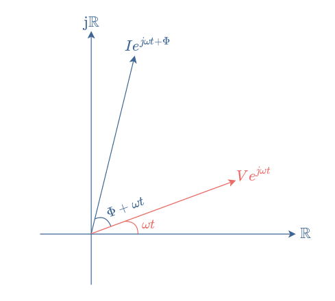
However, we mostly prefer to draw the diagram such as presented in Figure 2 since it establishes a reference and because the angle ωt is not relevant.
One last comment before focusing on the phasor algebra would be to add those phasor diagrams that are only possible to draw when the signals are of the same frequency. The phase shift between two signals that are not synchronized isn’t constant and therefore the phasor diagrams at different times t1 and t2 would change.
Phasor algebra
Addition and subtraction
Phasor diagrams are very convenient when we need to add and subtract two signals that are not in phase.
When two signals are in phase, let’s say V1(t)=v1sin(ωt) and V2(t)=v2sin(ωt) it is indeed easy to addition them : V1(t)+V2(t)=(v1+v2)sin(ωt). However, when the signals are not in phase, this procedure does not work for the reasons mentioned in the introduction.
Consider two voltages signals of same frequency phase-shifted of Φ radians: V1(t)=v1sin(ωt) and V2(t)=v2sin(ωt+Φ). Figure 4 shows the procedure to add these two phasors :
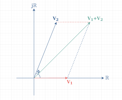
Since the addition is a commutative operation, two ways of proceeding will lead to the same result: from V1 we add V2 (dashed blue line) or from V2 we add V1 (dashed red line).
If we consider the grid of Figure 4 to represent 1 V for each division, we can then determine the new amplitude and phase of V1+V2. We can see that V1+V2 can be written as a complex number of 5+5j. The amplitude of the output is, therefore √(52+52) = √50 ≈ 7 V and the phase is 45° or π/4 radians. Finally, we can say that V1+V2=7×sin(ωt+π/4).
The procedure to subtract these two signals is the same, however, the subtraction is not commutative. This means that the result of V1-V2 or V2-V1 is different, as we are used to for real numbers :

The amplitude of V1-V2 or V2-V1 is identical and in our example would be equal to √(52+12) = √26 ≈ 5.1 V. The phase of V1-V2 is equal to atan(-5/1) ≈ -79° and the phase of V2-V1 is -79+180°=101°.
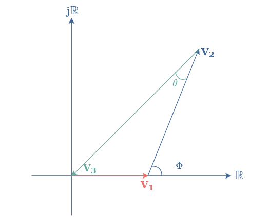
The phasor diagram is particularly helpful for some specific problems. Indeed, consider two signals of the same frequency V1 and V2 that are phase-shifted of an angle Φ, such as in Figure 4.
The problem is: which phase and amplitude are needed for a third signal V3 that results in destructive interference such as V1+V2+V3=0 ?
The phase diagram quickly and intuitively solves this problem :
Differentiation and integration
The differentiation or integration of phasors can help to solve differential equations related to first or second-order circuits.
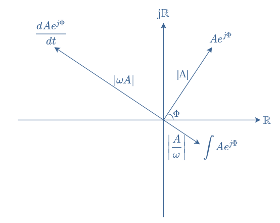
In order to understand how a differentiation or integration can be represented in a phase diagram, we start from the complex form and consider a phasor Aej(ωt+Φ).
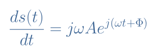
The differentiation of s(t) is given by the expression in Equation 4 :
The integration of s(t) is given by the expression in Equation 5 :
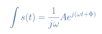
The imaginary unit j can be rewritten ejπ/2, therefore the differentiation operation is similar to multiplying the phasor by ω and proceed to a rotation of +π/2 rad or +90°. The integration is similar to multiplying the phasor by 1/ω and proceed to a rotation of -π/2 rad or -90° such as illustrated in Figure 7 :
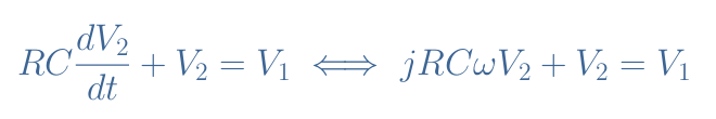
Consider an RC series circuit in which input voltage is the sine reference V1=v1ejωt and the output voltage is the unknown V2.
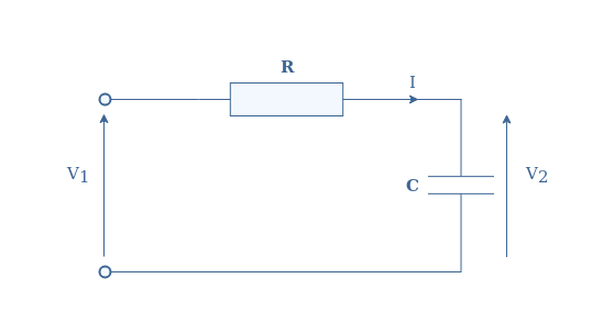
The voltages are linked by the following differential equation, which can be written in the classical form (left of the equivalence symbol) or with the phasor notation (right) thanks to the formula of derivation :
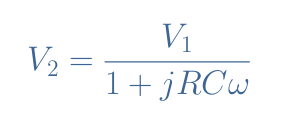
From this equation, we can express the unknown V2 as a function of the reference voltage :
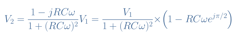
Which can be rewritten by multiplying the numerator and denominator with the complex conjugate :
From this expression, we can represent the phasors of the RC circuit in a phase diagram in Figure 9 and proceed to the addition of two phasors in order to draw V2 :
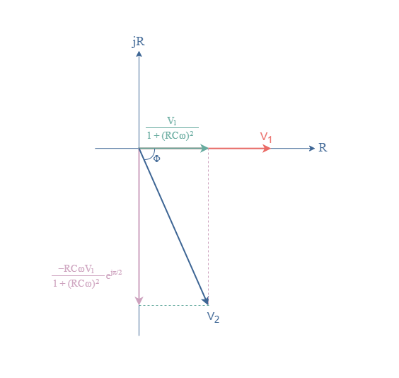
Both the amplitude and phase of V2 can be measured from this phase diagram with the same procedure that has previously been explained.
Conclusion
This tutorial has shown us a new method to represent and realize algebra on AC signals which is called phasors. A phasor can be both represented by a complex notation and also graphically in the complex plane as a vector which norm represents the amplitude and angle the phase of the signal.
When representing two or more signals in the same phase diagram, one of the signal always play the role of reference with a phase of 0°, aligned with the real number axis. The addition operation is commutative and can, therefore, be realized in two ways that lead to the same result. The subtraction is realized such as the addition but is not commutative.
Moreover, we have seen two other useful operations: differentiation and integration. In a phase diagram, the differentiation is equivalent to a positive rotation of 90° with multiplication by the frequency, the integration is equivalent to a negative rotation of 90° with a division by the frequency. These two operations are helpful in order to solve differential equations intervening in RC and LC circuits for example.