AC Waveform and AC Circuit Theory
Introduction When talking about current or voltage, these signals can be fitted into two main categories : DC and AC. DC states for "Direct Current", this definition regroup the signals that are constant in time : their amplitude and sign (+ or -) remain unchanged.
Introduction
When talking about current or voltage, these signals can be fitted into two main categories : DC and AC. DC states for “Direct Current“, this definition regroup the signals that are constant in time : their amplitude and sign (+ or -) remain unchanged. AC states for “Alternating Current“, these signals are alternating between positive and negative values, periodically at a certain frequency. AC signals should not be mistaken with variable signals that present no pattern in their evolution over time.
In this tutorial we will explore in three sections the topic of AC waveforms. In the first section, a general presentation of AC signals is given along with important definitions associated with. A second section will deal more specifically about the generation of AC signals and the important components present in the AC circuitry. Finally, a third section focuses on the AC power application, including mathematical definitions and the importance that AC signals play in the distribution of domestic power.
Presentation
AC signals have many shapes from sinusoidal to triangular, square, ramp wave etc … Despite their various shapes, they present one important similarity : the periodicity. In Figure 1, different shapes of AC waves are represented in blue along with their periodical pattern in red that highlights the periodicity.
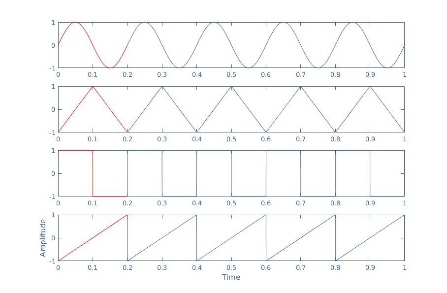
We can now introduce two linked and important definitions : the frequency and the period. As seen in Figure 1, the elementary pattern (in red) is reproduced for each signal five times during one unit of time (one second). This quantity is called the frequency (f) and it is expressed in Hertz or invert of a second (Hz=1/s).
The period (T) is a similar definition and is equal to the invert of the frequency : T=1/f. It represents the duration of an elementary pattern, and in our example, we can see that this duration is 0.2 s which is indeed equal to 1/(5 Hz).
It is worth mentioning that among the different shapes of AC signals represented in Figure 1, the sine wave is by far the most used. Triangular or square signals can be found in specific domains such as in acoustic amplification.
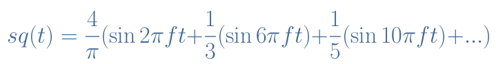
Moreover, sine wave have the property to be the “building blocks” of any other AC signals according to Fourier’s analysis. Indeed, any periodical signal can be written as a serie (an infinite sum) of sine functions. An approximation of an AC signal can however be obtained with the first terms of the serie. For example, an approximation with the three first terms of a the square signal sq(t) from Figure 1 with f=5 Hz is, as already mentioned in a previous article :
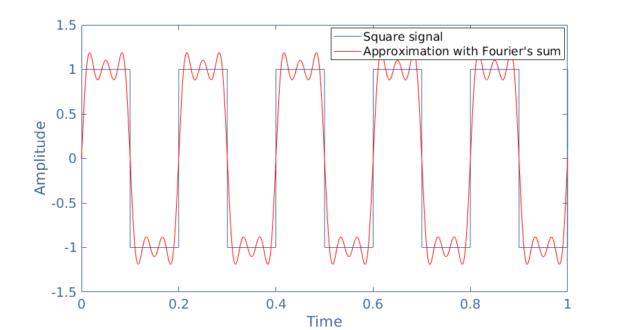
We can indeed confirm it by plotting on the same graph the original square signal with it’s approximation :
AC generation
Turbine-based generation
In the modern society, AC generation can be done with many different infrastructures : dams, nuclear power plant, coal plant, wind turbines … Despite the different sources of energy they use, these infrastructures generate an AC signal with the same principle.
The method to generate AC electricity is called turbine-based generation and transforms in two steps a primary energy (fossil fuels, wind, water movement …) into an AC power signal. The intermediary step consists in transforming the primary energy into the rotation of a turbine. The flowchart of this generation is presented below in Figure 3 :
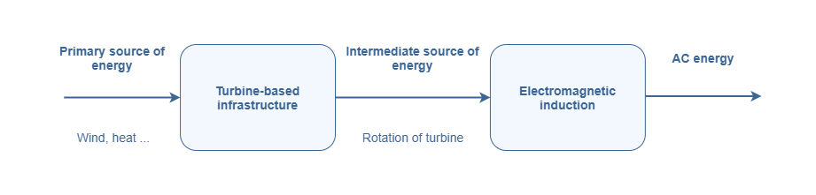
As seen in Figure 3, the transformation of energy is based on the turbine, which is a mechanical component and also an electromagnetic effect known as induction.
Let’s clarify what the turbine and electromagnetic induction consists of. Without going too much into the details, a turbine has two main components : a rotor and a stator. The rotor is the part in rotation, this rotation is generated by the primary source of energy that can be harvested from our environment. The stator is stationary and surrounds the rotor as a ring, it is in the stator that will generate the AC energy. This architecture is illustrated in Figure 4 :
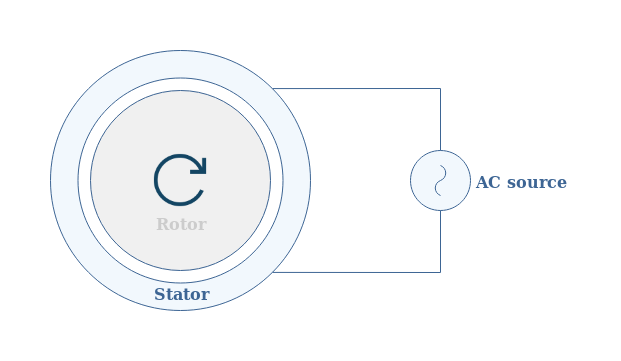
Both the rotor and stator can either be permanent magnets, having the property of generating a constant magnetic field, or electromagnets that generate the same field when a current passes through them.
The creation of an electric signal in the stator comes from the fact that a variable magnetic field is generated thanks to the rotation of the rotor. An opposite magnetic field is generated in the stator via an electrical signal in order to moderate this cause. It is precisely this counter-acting electrical signal that becomes the AC source. This effect is known as the electromagnetic induction or Lenz’s law.
Transformers
Worldwide, electricity is distributed from the provider to the consumer in its AC form. As we will see in the next section, the reason why this is privileged and possible is the use of transformers in the AC circuitry.
A transformer consists in its simple description of a core that can transport a magnetic field and two windings (N1 and N2) symmetrically positioned around the core that constitute the primary (V1, I1) and secondary circuit (V2, I2) such as illustrated in Figure 5 below. This transfer is also possible thanks to the electromagnetic induction phenomenon.
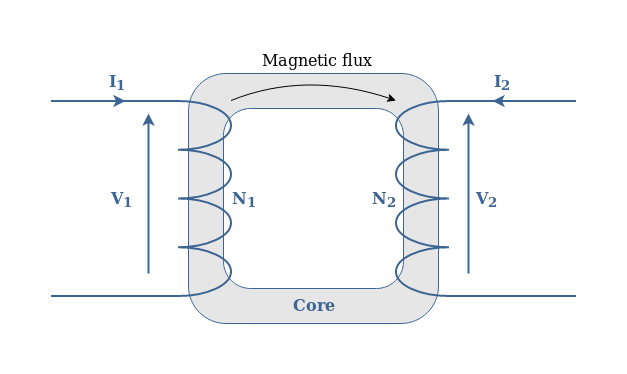
The most important fact to keep in mind about transformers is that they are able to change passively the amplitude of voltage and current of AC signals according to the following formula :
AC power
The RMS value
As we mentioned in the previous section, everyone, even a non-scientist is familiar with the AC electricity in our household. A part from a few exceptions, AC power is delivered to consumers at 120V or 220 V of amplitude and 50Hz or 60 Hz of frequency.
However, if you measure the mains voltage with a multi meter or oscilloscope the AC signal coming from your outlets (in Europe), you will see a sine wave with a top amplitude of 220×√2≈310 V. This maximum amplitude is called the Peak value whereas the 220 V we are familiar with is called the RMS value (for Root Mean Square).
In order to understand better this concept, let’s consider a positive half wave of a sine signal and intermediate values in t1, t2, … represented in Figure 6 :
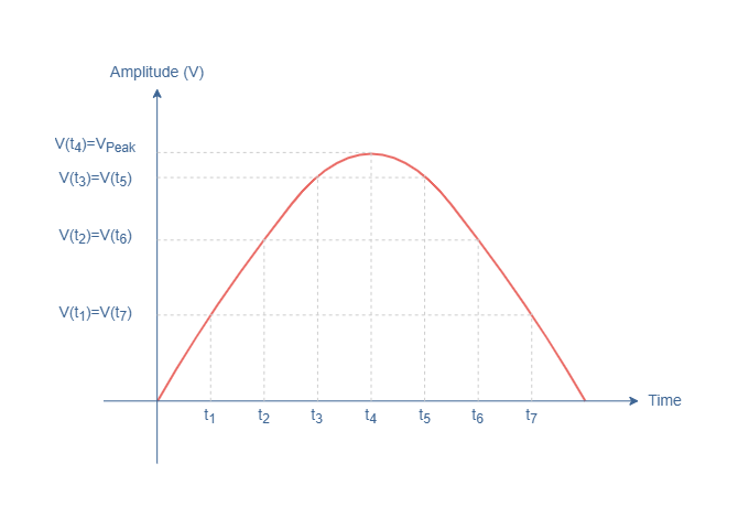
The RMS value for any periodic signal (including sine signals) is defined on a half wave such as :
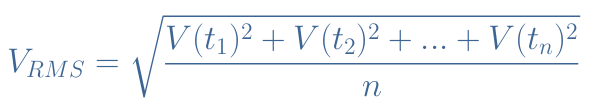
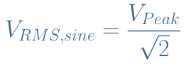
Due to the particular symmetry of the values V(ti) highlighted in Figure 6, the RMS value for sine waves is always equal to :
So why is the RMS value so important ? Because it is the equivalent DC amplitude that is dissipated in an output resistance (TV, microwave …). It represents the average value that will indeed be seen as a DC signal by any appliance we use.
Distribution of power
This final subsection will focus around one question : why is electricity distributed in AC form instead of DC ? This question can be answered in two parts that are linked : less losses are observed at higher voltage and AC electricity can be transformed (via transformers).
In order to understand the first affirmation about the losses, let’s consider a transmission line of resistance R where an AC power signal (V, I) is carried. Note that V≠R×I since the AC signal generation precedes the transmission. The input power is Pi, the output power is Po and the power losses are noted Pl.
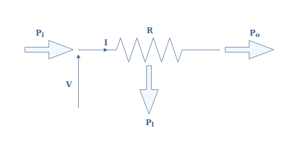
The power values satisfy the following equations :
- Pi=V×I
- Pl=R×I2
- Po=Pi-Pl
The efficiency of this line is given by the ratio Po/Pi=1-(R×I)/V. The transmission efficiency is thus improved if the voltage is increased. This is the reason why transmission lines do not carry an AC signal directly in 220 V RMS value because the losses would be too important. Power is rather distributed at around a few hundreds of kV to minimize the losses of the transmission line.
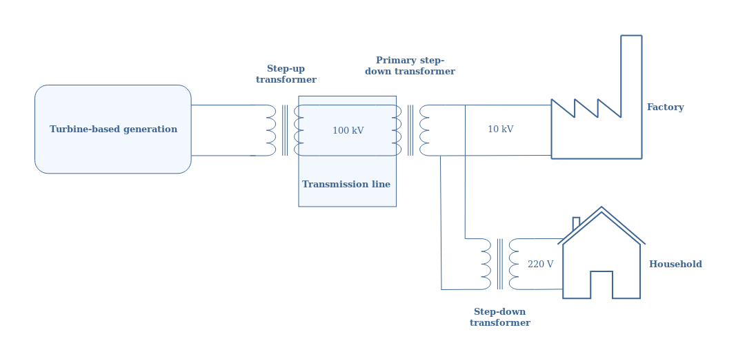
However, the signal used in domestic application is much lower and this is where transforming the signal is extremely necessary and interesting. Indeed, the use of transformer allow the electricity providers to either step-down or step-up the voltage such as illustrated in the following Figure 8 that indicates the orders of magnitude at every stage of the distribution :
Now we have understood why electricity is distributed in AC waves : transformers allow to easily step-up or down the power signal in order to distribute it to a large number of customers and to avoid unnecessary losses during its transportation.
Conclusion
This tutorial has first of all introduced us to the concept of AC wave signals. These signals can be characterized by 3 factors :
- The amplitude peak : it is the maximum that the signal reaches from its reference (0 V or 0 A).
- The frequency or period : it denotes how fast the signal repeats itself
- The pattern : it gives the shapes of the signal (sine, triangle, square …)
Among all the different AC signals that can be generated, sine waves are the most important because they are naturally generated by turbines and any periodical signal can be written as a Fourier’s serie.
The generation of such electric signals has been presented in two parts in a second section. We have seen that a turbine-based generation is the system exploited in any infrastructure to harvest a primary source of energy and convert it into AC energy. This is possible thanks to a physical law called the electromagnetic induction that is responsible for generating an AC current when a magnet rotates into another magnet.
In the second part, another important component of the AC power circuitry is present : the transformer. It also works thanks to the induction phenomenon and is useful to passively transform the voltage and current of a signal.
Finally a last section deals more specifically with the AC power topic. A first paragraph explains the meaning of the RMS value of a periodical signal : it representσ the effective power dissipated in a load by an AC signal. A last subsection is here to explain that AC waves are preferred over DC for the distribution of electricity since their voltage can easily be stepped-up to transport the power without losses in transmission lines, or stepped-down to provide the specific energy needs of different consumers.