

Binary Subtractor
- Muhammad Shahid
- m_shahid@live.co.uk
- 12 min
- 612 Views
- 0 Comments
- 38 Likes

Binary Subtractor
The Binary Subtractor is a combinational logic circuit that performs an arithmetic operation of subtraction on binary numbers. The output of a Binary Subtractor is the difference (X – Y) resulting from subtracting the two binary inputs (X & Y). It is one of the important arithmetic combinational logic circuits just like Binary Adder, discussed in the previous article.
As the Binary Addition results in two outputs i.e. Sum (S) & Carry (C), likewise, a Binary Subtraction also results in two outputs but, are termed Difference (D) & Borrow (B). In the Addition operation, the Carry (C) indicates an addition exceeding the maximum allowed value/ number depending on the number system. For example, in Denary it is nine (9) whereas it is one (1) in the case of the Binary number system. However, in Subtraction, a Borrow (B) indicates when the subtrahend (to be subtracted number) is greater than the minuend (number from which another number is subtracted). In this case, a borrow is taken by that number of the minuend from the next column (next significant) to output a difference which is then returned back.
An arithmetic operation of subtraction between two numbers is represented by a minus (-) symbol placed on the rightmost side of the subtrahend. In the following denary subtraction, a borrowing concept has been explained.
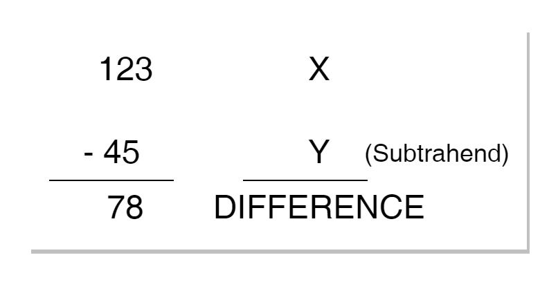
It is known that units are subtracted from units, tens from tens, hundreds from hundreds, and so on, just like the way, an addition is carried out. In this subtraction, units (first column) cannot be subtracted directly as five (5) is greater than three (3), and a borrow from minuend’s tens (next column) is taken by the unit to carry out the subtraction. This results in a difference of 8 (13 – 5) and a value of 1 after taking borrow from 2 in tens (next column). Afterward, tens of both numbers are subtracted, accordingly, and so for hundreds.
Binary Subtraction
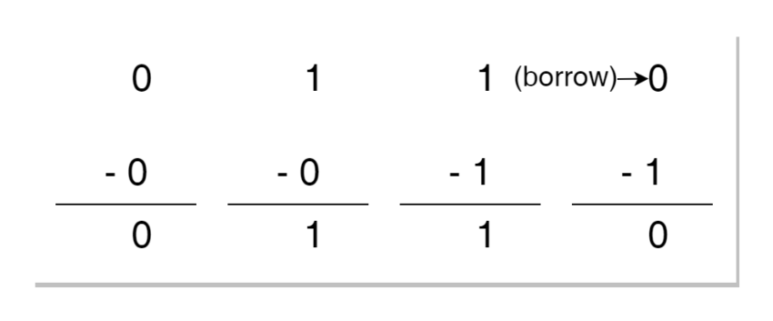
The subtraction of Binary numbers follows the same procedure described above for Denary numbers. A Binary number is a Base-2 number and, as such, a Binary Digit (bit) can have only two (2) values. So, a bit of a binary number can have only two distinct values i.e. 0 or 1. As such, in Binary, the maximum allowed value for a digit is one (1). A subtraction of single Binary Digits (Bits) results in 0 – 0 = 0, 1 – 0 = 1, 1 – 1 = 0, and, 0 – 1 = 1 which requires a borrow. A borrow taken by 0 results in 10 (2 in Denary). The subtraction of single bits is explained below.
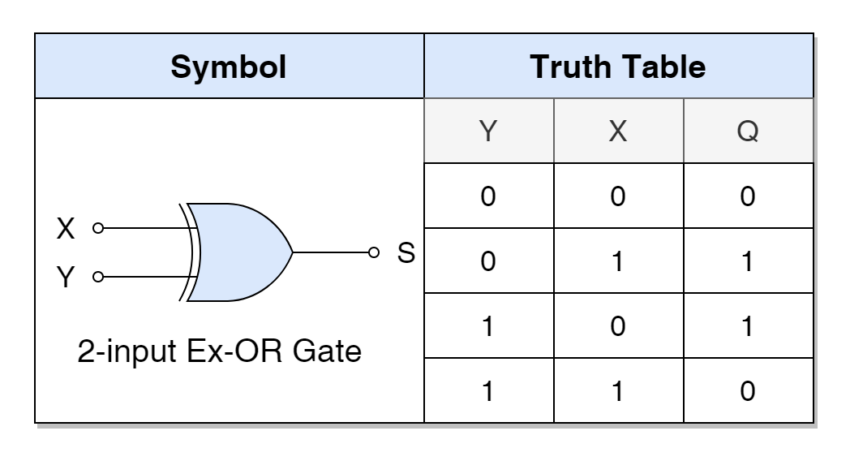
It is obvious from the above subtraction results of single binary digits that their combination resembles the truth table of an Exclusive-OR (XOR) gate when the borrow bit is ignored. A truth table of the 2-input Exclusive-OR (XOR) gate is illustrated below.
In Binary Adder, an Exclusive-OR (XOR) gate is used to produce Sum (S), and Carry (C) is needed when both digits are equal to 1. The generation of the Carry (C) bit was carried out using an AND gate. However, in Binary Subtraction, a Borrow (B) bit is to be generated when minuend & subtrahend are equal to 0 & 1, respectively. Looking at the required truth table or Borrow (B) depending on input combinations, this can be easily accomplished by ANDing the subtrahend and inverted-minuend. The logic circuit required for the generation of the Borrow (B) bit, is shown in the following figure.

Half Binary Subtractor
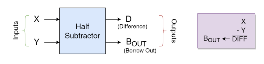
A Half Binary Subtractor is a combinational logic circuit that performs subtraction on two single binary digits (bits) producing Difference (D) and Borrow (B) bits. A Half Binary Subtractor can be constructed by combining an Exclusive-OR (XOR) gate and borrow bit generation described above. A general block diagram of the Half Subtractor is given below:
The resulting Truth Table of this Half Binary Subtractor along with the logic circuit is also illustrated below.
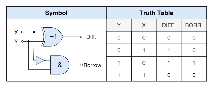
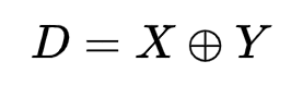
It is obvious from the Truth Table and logic circuit that Difference (D) is the result of the Exclusive-OR (XOR) gate. Whereas, the Borrow (B) is the result of NOT-AND combinational logic. The Boolean Expressions for these outputs are:
Difference (D) bit:
Borrow (B) bit:
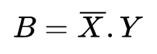
The above expression of Difference (D) bit is exactly similar to the Sum (S) expression of a Half Binary Adder as both expressions result from the usage of an Exclusive-OR (XOR) gate. The expression of the Borrow (B) bit is also very similar to the Carry (C) expression of Half Adder and the minor difference is due to the inversion of the minuend. This is the only difference between a Half Adder and a Half Subtractor and a Half Subtractor can be created from a Half Adder by inverting the minuend.
The Half Subtractor has one of the main disadvantages of not taking a Borrow (as an input) from the previous (less significant) Half Subtractor. A “Borrow-in” is essentially required for subtracting numbers with more than one digit. A Half Subtractor having provision of Borrow-in from previous subtraction is called a “Full Binary Subtractor”.
Full Binary Subtractor
A Full Binary Subtractor has an additional input of “Borrow-in”, as compared to Half Binary Subtractor, for taking into account “Borrow-out” from the previous Half Subtractor. A block diagram of a Full Binary Subtractor has been shown in the following figure.
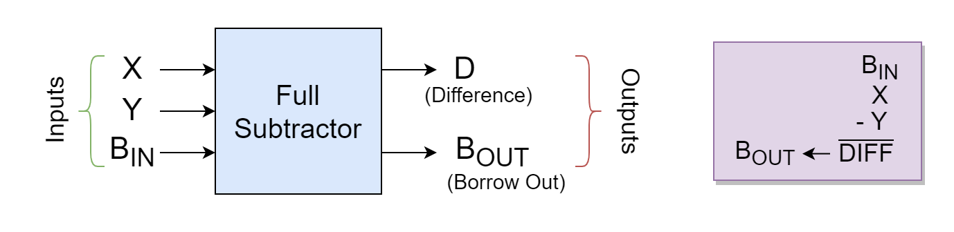
The Full Binary Subtractor performs subtraction on three inputs (X, Y, & BIN) and produces outputs (D, & BOUT). The process of subtraction is carried out in two steps by Half Binary Subtractors which are cascaded together so that the first Half Subtractor (BOUT) passes its “Borrow” to the second Half Subtractor (BIN). This cascading of Half Subtractors is illustrated below.
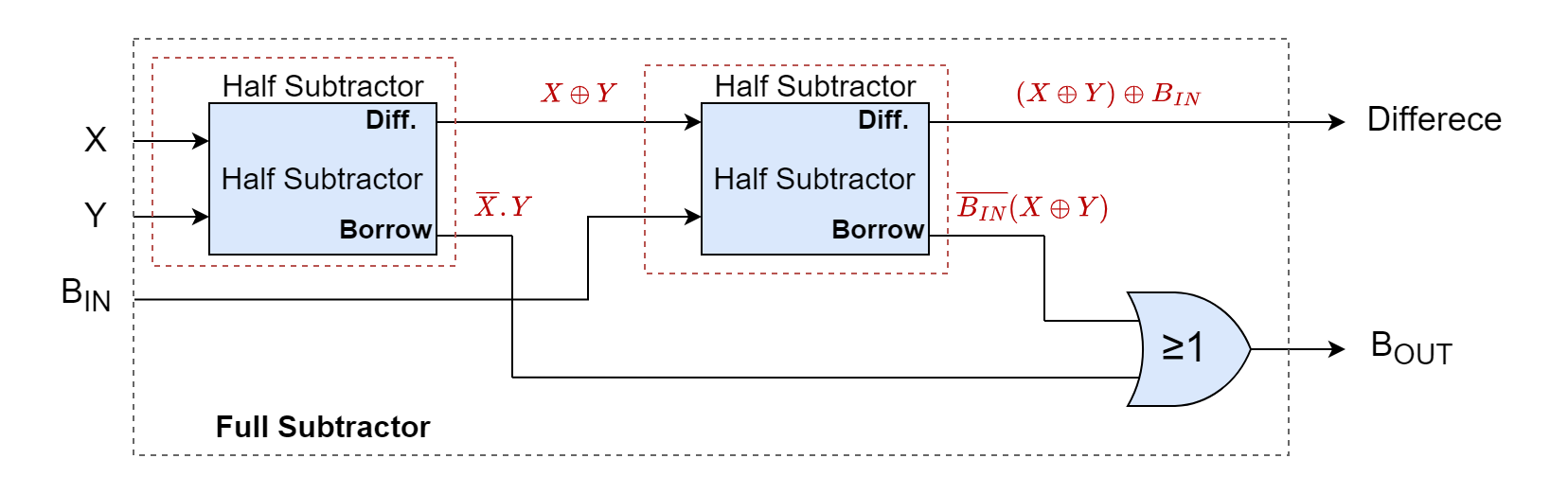
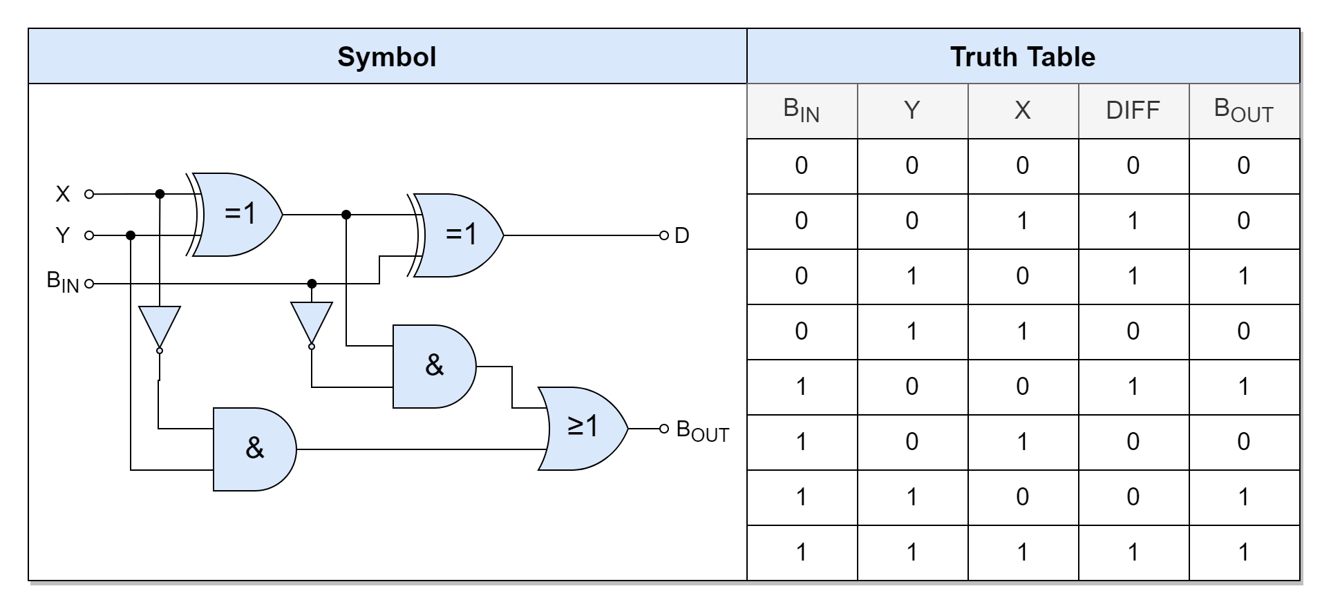
The Full Binary Subtractor comprises two Half Binary Subtractors which are cascaded and the Borrow Out (BOUT) is generated by using the OR gate on individual Borrow of each of the Half Binary Subtractors. As a Full Binary Subtractor has three inputs so its Truth Table has a total of eight (8) input combinations. The Truth Table of the Full Binary Subtractor has been given below.
Expressions for outputs of a Full Binary Subtractor are as follows:
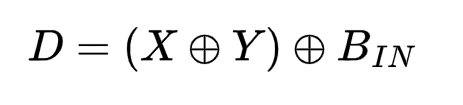
Difference (D) bit:
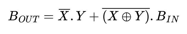
Borrow Out (BOUT):
n-Bit Binary Subtractor
Using a Full Binary Subtractor, a Binary Subtractor of larger binary numbers can be constructed by following the same method of cascading Full Binary Adders. The Borrow-out (BOUT) of the first Full Binary Subtractor is connected with the Borrow-in (BIN) of the next Full Binary Subtractor and the process is repeated for the required number of bits to be subtracted. Using this cascading, an n-bit Binary Subtractor can be constructed which has an inverted input compared to n-bit Binary Adder.
Binary Subtractor based on 2’s Complement
As explained above, using an n-bit Full Adder and “n” number of NOT gates, the process of addition becomes subtraction by using two’s (2’s) complement notation on subtrahend bits and Carry-in (CIN) pulled “HIGH” as shown in the following figure.
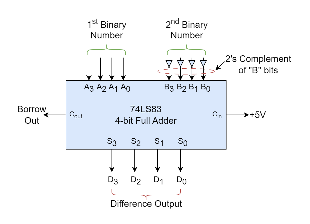
In this way, commercially available 4-bit Full-Adder ICs such as CD4008 (CMOS) and 74LS283 (TTL) can be utilized to perform 4-bit subtraction. Using a two’s complement (-Y) and then adding in X equals X + (-Y) which is equivalent to X – Y. In order to revert to the original Addition function, Carry-in (CIN) is set to “LOW”, simply, and setting of CIN to “HIGH” or “LOW” shifts the function between addition or subtraction.
Conclusion
- A Binary Subtractor is a combinational logic circuit that performs the arithmetic operation of subtraction on binary numbers.
- A Binary Subtractor produces two outputs of Difference (D) and Borrow (B). The Borrow (W) is generated when a subtrahend is greater than minuend.
- A simple single-bit Subtractor can be constructed using an Exclusive-OR (XOR), AND & NOT gates. In this construction, Exclusive-OR (XOR) gate produces Difference (D) and NOT-AND generates Borrow (B). This construction is termed a Half Binary Subtractor.
- A Full Binary Subtractor is constructed by cascading two Half Binary Subtractors. A Full Binary Subtractor can take in Borrow-in (BIN) from a previous Full Binary Subtractor’s Borrow-out (BOUT). This enables Full Binary Subtractors to be cascaded with each other.
- Subtraction of larger binary numbers (n-bit) can be accomplished by cascading the required number of Full Subtractors.
- A Full Binary Adder can be converted into a Full Binary Subtractor by inverting one of the inputs. As such, commercially available 4-bit Full-Adders (CD4008 &74LS283) can be used for subtractions purpose using two’s complement of the subtrahend and setting Carry-in (CIN) to “HIGH”. Setting Carry-in (CIN) to “LOW” resumes the addition function.
Please follow and like us:
Subscribe
Login
0 Comments


