Voltage Sources
Introduction In this tutorial, we present in detail the architecture, functioning, and use of an important electronic element known as the voltage source. We first present the base concept which is the ideal voltage source and an introduction to the alternators and batteries is given since they represent the most common types of AC/DC voltage sources.
Introduction
In this tutorial, we present in detail the architecture, functioning, and use of an important electronic element known as the voltage source.
We first present the base concept which is the ideal voltage source and an introduction to the alternators and batteries is given since they represent the most common types of AC/DC voltage sources.
Further, we highlight that these elements, like their names, suggest it, are ideal and therefore not found in real circuits, this is why we introduce and discuss the real voltage sources. Moreover, we establish some connection rules to be followed in order to properly implement voltage sources in a circuit.
Dependent sources are detailed in a third section where we will see that some voltage sources can be controlled by a voltage or current input.
Presentation
Alternators
A voltage source is an electric generator, and it produces an electromotive force from a different form of energy. The most common voltage sources are alternators and batteries.
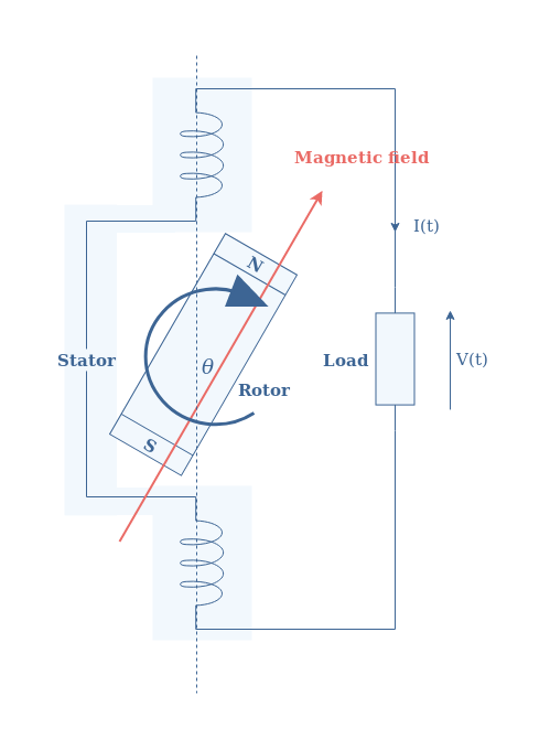
Alternators convert energy by mechanical rotation to produce an AC signal and their functioning, thanks to the electromagnetic induction phenomenon is explained in the Sinusoidal Waveforms tutorial.
Batteries
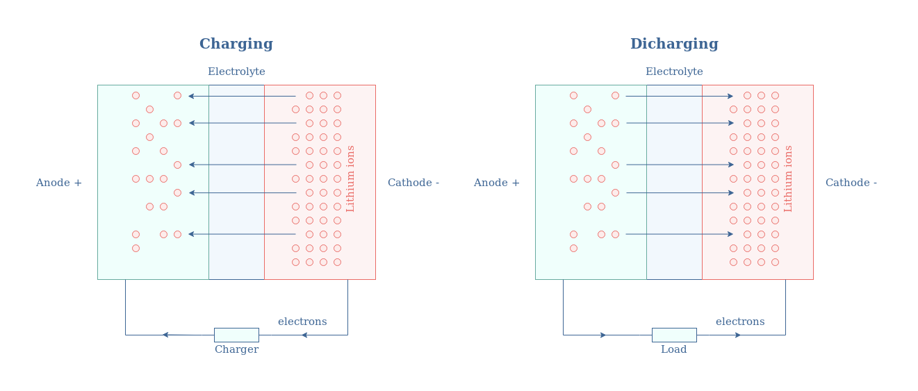
On the other hand, batteries convert chemical energy into a DC signal thanks to a reduction-oxidation reaction. One of the most common types is certainly the lithium-ion battery which function schematic is presented in Figure 2 below:
Ideal voltage sources
An ideal voltage source is an element that can supply a constant value of voltage regardless of the current flowing through the output load. This definition is both valid for DC or AC voltage sources, in the AC case, it is the RMS value that is kept constant.
The following Figure 3 illustrates how a voltage source is usually drawn in a circuit diagram and its related voltage/current characteristic. Note that no distinction is made between a DC or AC source, the labels V and I can therefore both refer to the DC or RMS values.
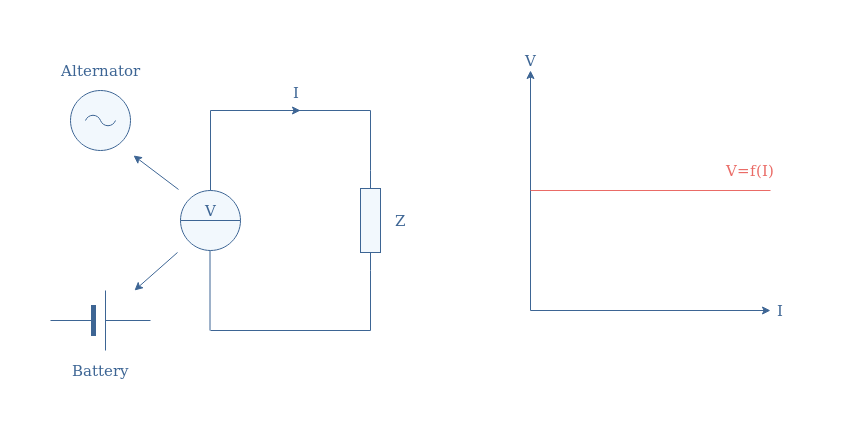
It is important to remember that ideal voltage sources are characterized by a flat V/I characteristic. The consequence of such a characteristic is that an ideal source can theoretically supply any amount of power (V×I) without any losses.
This affirmation is of course not true, in real sources the power supplied is limited by losses which origins are internal to the source as we will see in the next section.
Real voltage sources
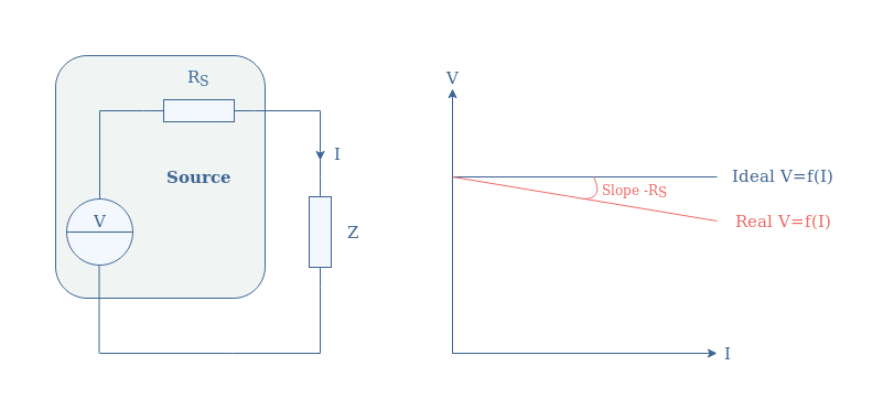
As stated previously, real voltage sources do not present a flat V/I characteristic. These power losses affecting the source are modelized by an internal resistance (or source resistance) noted RS and placed in series with the voltage source.
Figure 4 illustrates the circuit diagram of a real voltage source along with its voltage/current characteristic:
The value of RS is an important parameter to characterize voltage sources, it is also known as the voltage regulation.
Connection rules
Some connection rules are necessary to keep in mind when integrating voltage sources in a circuit.
The first and most important one is to not place the voltage source in a short-circuit, we can also say to not short the source, such as illustrated in Figure 5.
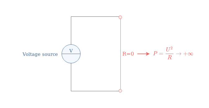
Shortening a voltage source is actually equivalent to imposing a potential difference V on a resistance equal to zero, which results in an active power tending to infinity. In practice, the internal resistance of the source and the connection wires will simply be submitted to a strong current resulting in their melting or irreversible damage to the source.
The second rule concerns parallel connections between 2 or more voltage sources. It is never recommended to connect voltage sources in parallel without any components in between, even when their value is strictly identical.
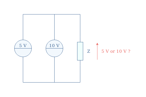
The first reason why the circuit in Figure 6 is not realized is that a short circuit can be produced between the sources. In this example, a potential difference of 5V is generated between the wire connecting the sources, provoking a fast increase of the current since the equivalent resistance is zero.
Moreover, the output load Z will choose the source that can deliver the necessary power faster. Only the 10 V source will work, leaving the 5 V source being unproductive.
Finally, connecting voltage sources of equal or different values in series is allowed and frequently encountered to connect accumulators together (called a battery) in order to produce a higher voltage such as illustrated in Figure 7.
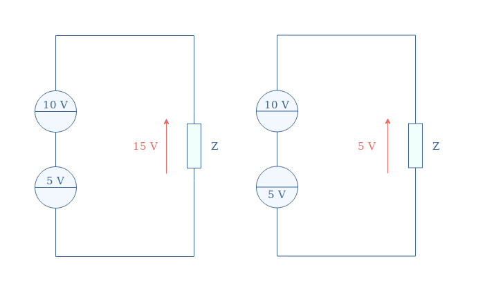
The resulting output voltage at the terminals of the battery of sources is the algebraic sum of the different sources used. When the sources are providing a voltage in the same direction (left circuit), the absolute values are in addition, when the directions are different (right circuit), the absolute values are subtracted.
Dependent sources
The values of the voltage sources presented in the previous sections are fixed and do not depend on any parameter or element of the surrounding circuit, they are therefore qualified as independent sources.
We present in this last section a different type of voltage source, known as dependent sources, which value is correlated to a parameter.
Dependent sources are quadripole components symbolized with a diamond shape in circuit diagrams:
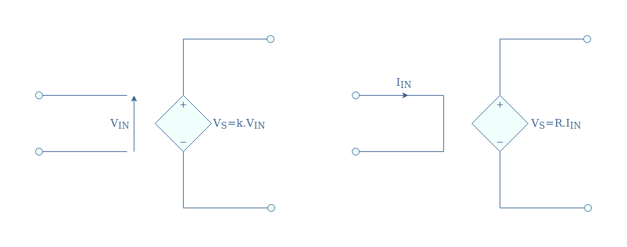
In the case of voltage sources, the control parameter can either be an input voltage (VIN) or a current (IIN). In the first case, we refer to it as a Voltage Controlled Voltage Source (VCVS), in the second case, we mention it as Current Controlled Voltage Source (CCVS).
Voltage Controlled Voltage Source (VCVS)
For VCVS, a dimensionless factor (k) called the gain links the input voltage and the output that the source generates.
A VCVS is always controlled by a more or less complex circuit that provides an input voltage which will generate an output voltage to power an output load. A typical VCVS circuit is illustrated in Figure 9:
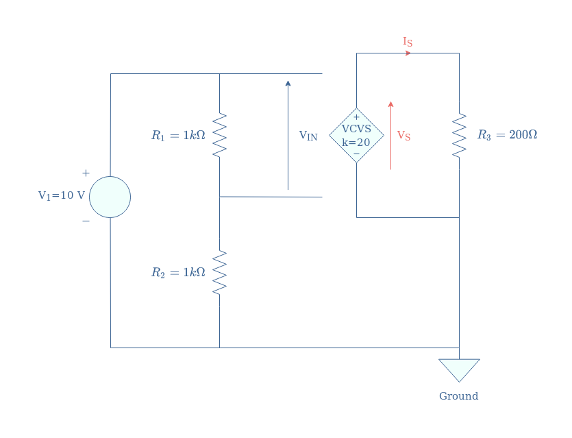
In this example, we want to show how to obtain the unknown output parameters VS and IS.
First of all, we can comment that the controlling stage consists of an ideal voltage source providing 10 V to a voltage divider circuit (R1 and R2). Since R1=R2, the output voltage of the voltage divider (or input of the dependent voltage source) is half of V1 and equal to VIN=5 V.
Since the gain of the VCVS is set to be 20, we can conclude that VS=20×VIN=100 V. The output current is simply computed with Ohm’s law: IS=VS/R3=0.5 A.
Current Controlled Voltage Source (CCVS)
For CCVS, the factor linking the input current to the output voltage is labeled R, which is not a coincidence since it is expressed in Ohm unit (Ω).
A typical CCVS can be designed similarly to the architecture presented in Figure 9 for the VCVS:
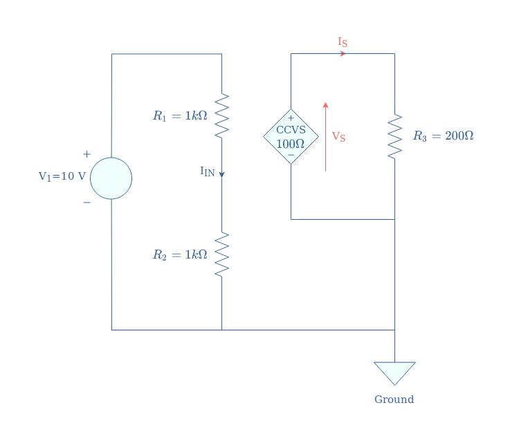
The input current IIN of the dependent voltage source is simply given by Ohm’s law: IIN=V1/(R1+R2)=5 mA.
The voltage delivered by the CCVS is found by multiplying this input current by the factor R: VS=R×IIN=0.5 V. We apply against Ohm’s law to find the output current IS=VS/R3=2.5 mA.
Conclusion
The most common devices that can be qualified for voltage sources are alternators and batteries. Alternators convert mechanical energy into an AC output thanks to the phenomenon of electromagnetic induction. On the other hand, batteries provide a DC output from a chemical source of energy.
Ideally, whether we deal with a DC or AC device, a voltage source should provide a stable and constant output value regardless of the output load, and therefore current that must be provided. Ideal voltage sources are defined by a flat voltage/current characteristic which implies that an infinite amount of power could be provided to a load.
However, voltage sources that can be found in real circuits are never ideal as they present an internal resistance (RS) that dissipates a fraction of the power they produce. This internal resistance is a modelization that reflects some dissipation phenomena, the component is not physically present in the design of the voltage source. Real voltage sources have a V/I characteristic defined by the function V=Videal-RS×I, when comparing it with the ideal characteristic, it presents a light slope of value -RS.
Some important connection rules are further given for voltage sources, shortening and associating voltage sources in parallel is not recommended since it can lead to a fast increase of the current which results often in burning wires or components. The series association of voltage sources is however allowed and commonly found to increase the total voltage output.
Finally, the last section of this tutorial presents the dependent voltage sources. The output of this type of source is controlled by an input that can be of two natures:
- Voltage Controlled Voltage Sources (VCVS) are controlled by a voltage input
- Current Controlled Voltage Sources (CCVS) are controlled by a current input
We present for each source a typical circuit and how to proceed to compute their outputs.


