Maximum Power Transfer
Introduction When engineers design electronic circuits, they keep track of many different parameters, but one of the most important is power. In a modern circuit, the power evolves during its many stages, and sometimes it needs to be increased with amplifiers due to much loss caused by dissipative elements.
Introduction
When engineers design electronic circuits, they keep track of many different parameters, but one of the most important is power. In a modern circuit, the power evolves during its many stages, and sometimes it needs to be increased with amplifiers due to much loss caused by dissipative elements.
It is usually preferred to maximize the power transfer between every stage of a circuit in order to avoid as much as possible any reamplification. This is, for example, the case with the transmission of information in the telecommunication domain.
In this tutorial, we focus on a simple but important concept called the Maximum Power Transfer Theorem (MPTT) which explains how power is most efficiently transmitted from a source to a receptor.
To introduce this concept, we will first make a simple observation on a Thevenin circuit in order to understand that the power transmitted depends on the resistor values. We also emphasize the distinction that needs to take place between the optimization of power transferred and the efficiency of the circuit.
In the second section, we explain the MPTT in the general case and prove it by providing a demonstration.
Finally, we focus on the Impedance Matching concept which is linked with this theorem and is an important technique used to optimize the power transfer.
Presentation
Consider a linear electrical circuit that can be reduced to a given Thevenin equivalent model VTh, RTh which is connected at its terminal to a variable load Z such as illustrated in the following Figure 1:
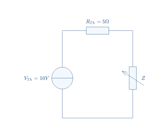
As shown in this Figure, we will consider specific values for VTh and RTh. The common current flowing into the circuit can be written thanks to Ohm’s law: I=VTh/(RTh+Z).
Since the power transmitted to the load can be expressed as PZ=Z×I2, we can develop this expression to write PZ as a function of Z and the known parameters of the circuit: PZ=(Z×VTh2)/(RTh+Z)2.
Figure 2 below shows the graph PZ=f(X) where X=Z/RTh, it is plotted thanks to a data software such as MatLab®:
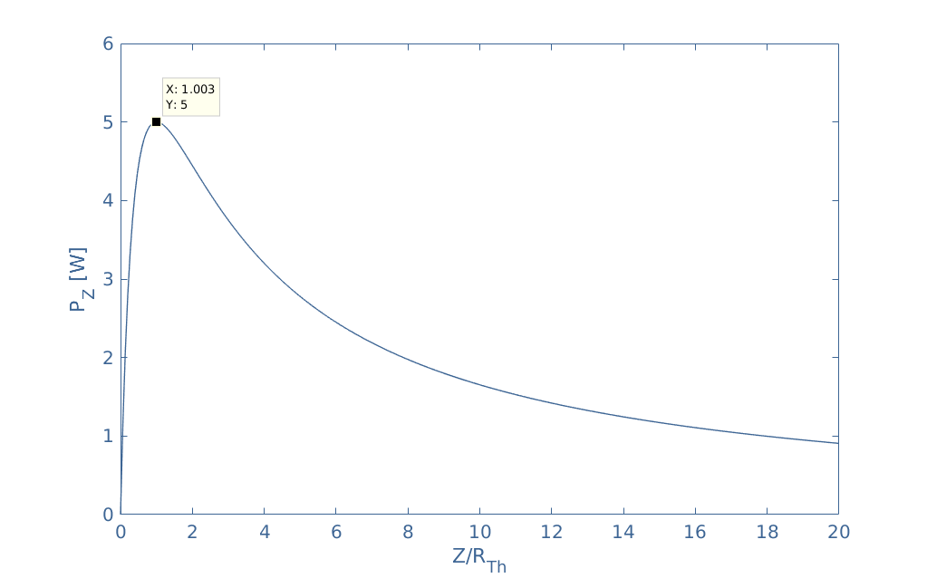
As highlighted in this Figure, it appears that the maximum power transmitted is reached for Z=RTh. This peak is however not very narrow since the power transmitted is still at 90% of the maximum value for a ratio X=2.
It is important to note that the maximum efficiency defined by the ratio η=PZ/PS, with PS being the power generated by the source, is not reached for X=1 which is exclusively the condition of maximum transferred power. This distinction is confusing and has already been quite detailed in one of our previous articles here: Input and Output Impedances of Amplifiers.
We can note that when the maximum transferred power is achieved, an efficiency of only 50 % is observed. This number can quite easily be explained by the fact that when RTh=Z, the dissipated power by the internal source resistor (RTh) is the same as in the load Z. Maximum efficiencies are reached when the inequality Z>>RTh is satisfied, in this case, no power is dissipated in the internal source resistor.
Maximum Power Transfer Theorem (MPTT)
In this section, we present the general form of the MPTT and furthermore propose a demonstration.
We propose the following Figure 3 as an illustration to refer to:
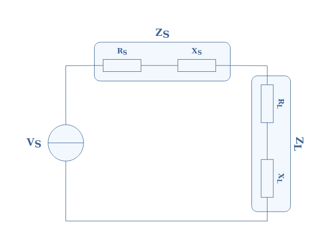
This circuit can either be considered as a Thevenin model, with VS=VTh and RS=RTh as the equivalent resistance of a circuit between a source and the load, or an unideal source with its internal impedance ZS=RS+jXS supplying a complex load ZL=RL+jXL.
The MPTT states that in order to maximize the power transferred to the load, an impedance matching is required. Two conditions must be satisfied for that:
- The reactances must be compensated, that is to say, XS=-XL
- The resistances must match, that is to say, RS=RL
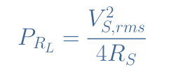
Since Re(ZS)=Re(ZL) and Im(ZS)=-Im(ZL), we can say that ZS and ZL are conjugated (see our tutorial about Complex Numbers for more information). Under this condition, the power delivered in the load RL is maximum and satisfies Equation 1:
Demonstration
The demonstration of this theorem consists of expressing the power in the load and find its maximum with a derivation operation.
We start by writing the module of the current across the circuit: |I|=|V|/(|ZS|+|ZL|). The power transferred to the load can be expressed with the RMS value of |I|, which square value is IRMS2=|I|2/2.
The power in the load satisfies, therefore:
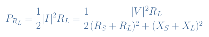
In order to maximize this fraction, we will minimize the denominator. The term of the reactances can be easily minimized and even compensated by choosing XS=-XL.
The expression of power can then be simplified:
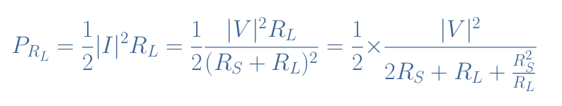
In order to minimize again the denominator D, we proceed to a derivation which is equalized to zero: dD/dRL=0. This derivation leads to -RS2/RL2+1=0⇒RS=RL.
However, when the derivative is equal to 0, either a maximum or minimum can be reached. In order to make sure that RS=RL is a minimum, we compute the second-order derivative d2D/dRL2=2(RS2/RL3).
For positive values of RS and RL, the second-order derivative is positive, which means that the denominator is a convex function (the same shape as the function x2). We can then confirm that a minimum is reached for RS=RL.
As a conclusion, the power in the load is maximum when RS=RL and XS=-XL. When these conditions are met, we can confirm that Equation 1 is satisfied.
Impedance Matching
We have briefly mentioned the term impedance matching in the previous section, here we explain how important this concept is, especially in the telecommunication domain.
The impedance matching technique is very used to optimize the signal transfer in transmission lines. A transmission line is a special double-wire that is adapted to conduct high-frequency signals with minimal losses.
They are usually represented by an equivalent circuit represented in the following Figure 4:
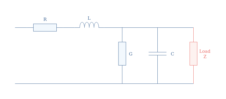
We need to note that the components shown in Figure 4 are not truly present in a transmission line, this representation exists in order to reflect the electrical behavior of the line.
The linear resistance and inductance of the line are represented by R and L. The properties of the material in between the two conductors are represented by the conductance G and the capacitor C. The load Z connected at the terminals of the transmission line can represent a television, an amplifier, a phone… etc
We define the characteristic impedance by ZC=√(L/C) which represents the impedance of the transmission line. Analogically with Ohm’s law, this particular impedance simply represents the ratio of the voltage and current propagating in the transmission line. A coaxial cable, for example, is a transmission line with ZC=50 Ω.
The expression of the characteristic impedance comes from the famous telegrapher’s equations, which itself, comes from the Maxwell’s equations of electromagnetism.
Ensuring that the power is optimally transferred from the source to the load is very important in this example. Matching the load Z with the characteristic impedance of the line indeed avoids reflections of the signal back towards the source, which would cause interference. In a phone line, for example, a poor impedance matching can be heard with echos.
Conclusion
For some circuits, a maximum of the power transferred is desired, especially in the telecommunication domain. We present in this article the Maximum Power Transfer Theorem (MPTT) which explains under what requirements this condition is met.
In the first section, we observe from a Thevenin circuit that the maximum power transferred is reached when both the resistor present in the circuit are equal. We also explain that it is important not to mistaken the maximum power transferred with the efficiency of the circuit, despite the similarities in their definitions.
In the second section, we detail the MPTT by explaining that two conditions are required in order to achieve the maximum power transferred. Not only the resistor must be equal but the reactances must compensate each other. Furthermore, a demonstration of the theorem is provided, which can help the reader to understand the difference between this theorem and the efficiency concept.
Finally, a small section details the concept of impedance matching in the telecommunication domain.


