Voltage Dividers
Introduction Sometimes, a precise value of voltage is needed as a reference or simply before a specific stage of a circuit that requires less power. Voltage dividers are a simple resolution to this problem as they take advantage of the fact that a voltage can be dropped across components put in a series configuration.
Introduction
Sometimes, a precise value of voltage is needed as a reference or simply before a specific stage of a circuit that requires less power. Voltage dividers are a simple resolution to this problem as they take advantage of the fact that a voltage can be dropped across components put in a series configuration.
The most common type of voltage divider is based on the series association of two resistors, we present in detail this type of configuration in the first section of this tutorial.
By keeping the same architecture, resistors can be replaced by reactive components such as capacitors or inductors. These different types of voltage dividers are presented in two other sections.
Presentation
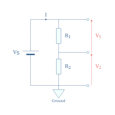
In Figure 1, we present the most common and simple configuration for a resistive voltage divider:
In the following, we will label this configuration “R1-R2“.
We can first of all note that according to Kirchoff’s Voltage Law, V1+V2=VS. This relation can be rewritten thanks to Ohm’s law into VS=(R1+R2)×I.
Since V1=R1×I, V2=R2×I, and I=VS/(R1+R2), we obtain in Equation 1 the following voltage divider formulas:
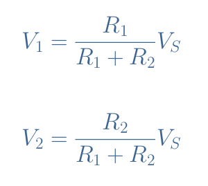
It is interesting to note that both dimensionless factors for V1 and V2 in Equation 1 can range from 0 to 1. As a consequence, both signals V1 and V2 can range from 0V up to the source value VS.
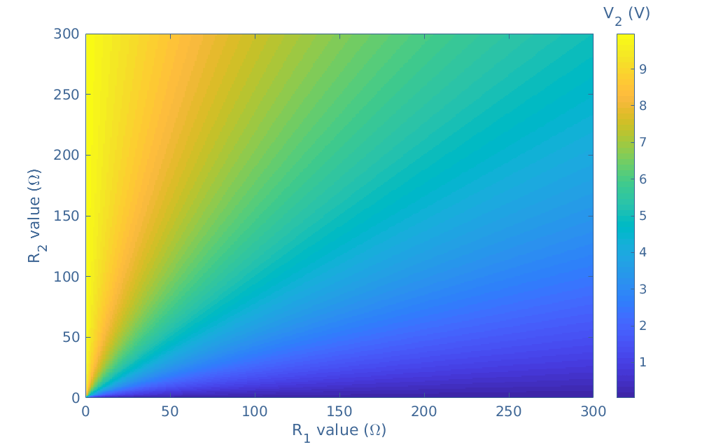
With a data program, it is possible to plot every possible value that V1 or V2 can take depending on R1 and R2 such as shown in Figure 2. For this example, we chose to plot V2 with VS=10 V and R1,R2=[0;300] Ω.
Often, voltage sources or current sources can only provide a fixed value of voltage or current. Some stages of a circuit, however, need lower values that the source is providing.
A simple voltage divider in which resistors values are appropriately chosen can provide any voltage value between 0 V and the source value, it constitutes a good solution to attenuate the source before a specific stage.
Another application in which resistive voltage dividers are suitable is the measure of high DC voltages. We illustrate this approach in Figure 3:
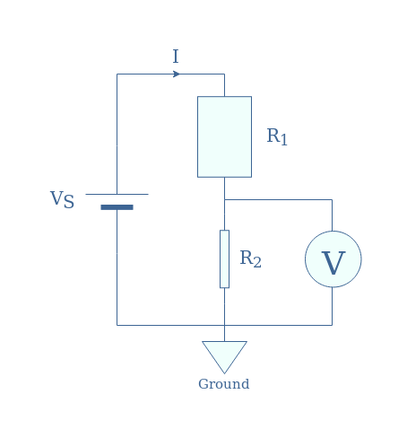
Note that the shape of the resistors is voluntarily modified to reflect the ratio R1/R2.
In order to protect the voltmeter (and its user) from measuring directly the high voltage VS, only a small fraction is measured by the voltmeter corresponding to R2/(R1+R2)×VS. The display is then corrected by multiplying the measurement by the same value that the high voltage was divided with.
For example, if R1/R2=99, the voltmeter measures only 1% of VS. The voltmeter will then display on the screen the exact value of VS by multiplying the measurement by 100.
Loaded voltage divider
We consider now the same voltage divider R1-R2 as presented in Figure 1 but with the additional presence of a load RL at the terminals of R2:
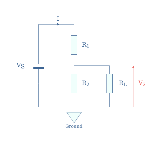
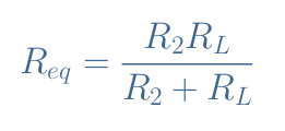
We will demonstrate the expression of V2. First of all, we express the equivalent resistance Req of the R2//RL parallel association:
We then apply the formula of the voltage divider (Equation 1) to the voltage divider R1-Req:
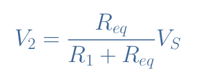
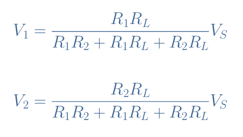
If we develop and rearrange this expression, we obtain V2 as a function of R1, R2, RL, and VS. Moreover, if the output load is instead connected to the terminals of R1, we can also write the expression of V1 similarly to obtain both formulas for the load voltage divider:
Voltage divider network
A voltage divider network is the association of three or more resistors in series that act as a voltage divider. In the following Figure 5, we illustrate a voltage divider network with five resistors:
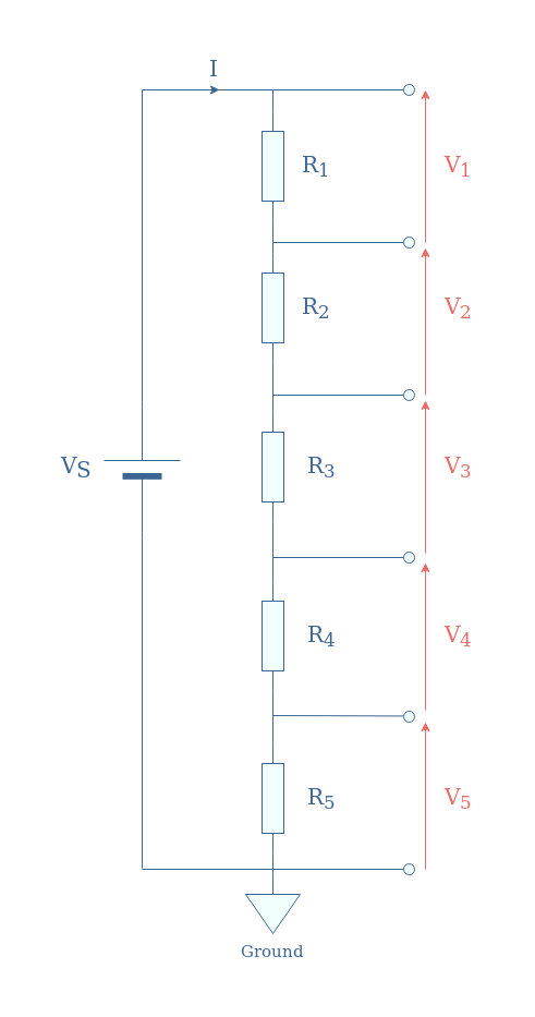
If we note Rseries=R1+R2+R3+R4+R5 the equivalent resistance for the series association of resistors, each voltage is given by Equation 3:
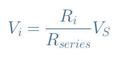
For a voltage divider network with N resistors, Equation 3 remains valid with Rseries=R1+R2+…+RN.
We need to conclude the sections about resistive voltage dividers by saying that they are highly inefficient because the resistors dissipate power by Joule’s heating. For obvious safety reasons related to these power losses, they are only used for low-power applications such as for example in microelectronics to drive MOSFET and Bipolar amplifiers.
For high-power applications, reactive voltage dividers are preferred since they do not dissipate to much power by Joule’s heating.
Reactive voltage dividers
Alternative voltage dividers can be based on a capacitor or inductor instead of a resistor, they are known as reactive voltage dividers.
Capacitive voltage dividers
Capacitive voltage dividers are based on the same architecture as presented previously in Figure 1 by replacing the resistors with capacitors. Since the reactance of capacitors is given by 1/Cω, capacitive voltage dividers only work in the AC regime.
The advantage of using capacitors is that they present much lower power losses at high frequencies than a resistor. Indeed, we have seen in the dedicated tutorial about AC Resistance that the AC impedance tends to become much higher than the DC impedance for high frequencies due to the skin effect.
Moreover, capacitive voltage dividers are usually used for voltages above 100 kV in RMS value. The reason why is that resistive voltage dividers dissipate too much heat for high voltages, while ideal or near-ideal capacitors store the energy in the form of an electric field and release it in the circuit.
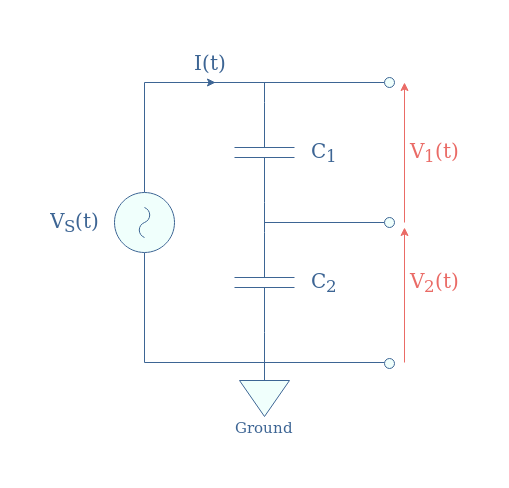
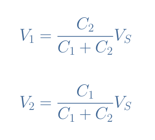
If we label V1, V2, and VS the RMS values of the voltages, it is easy to demonstrate again that they follow similar relations as presented in Equation 1. However, since the impedance here is proportional to 1/C, the subscripts of the numerator change:
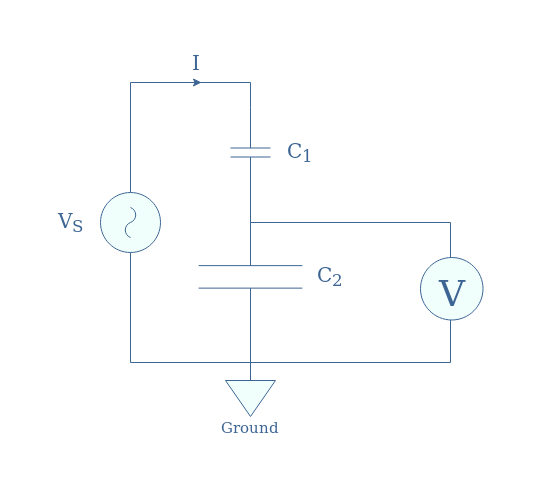
A similar circuit of Figure 3 by replacing the resistors with capacitors is suitable to measure high AC voltages. Since the voltage drop in a capacitor is proportional to 1/C, a large voltage drop will occur in the small capacitor C1:
Inductive voltage dividers
We do not encounter in the literature the term “inductive voltage divider” but we rather refer to this circuit as an autotransformer. An autotransformer is a single inductor with multiple tapping points, which can be seen as multiples inductors connected in series.
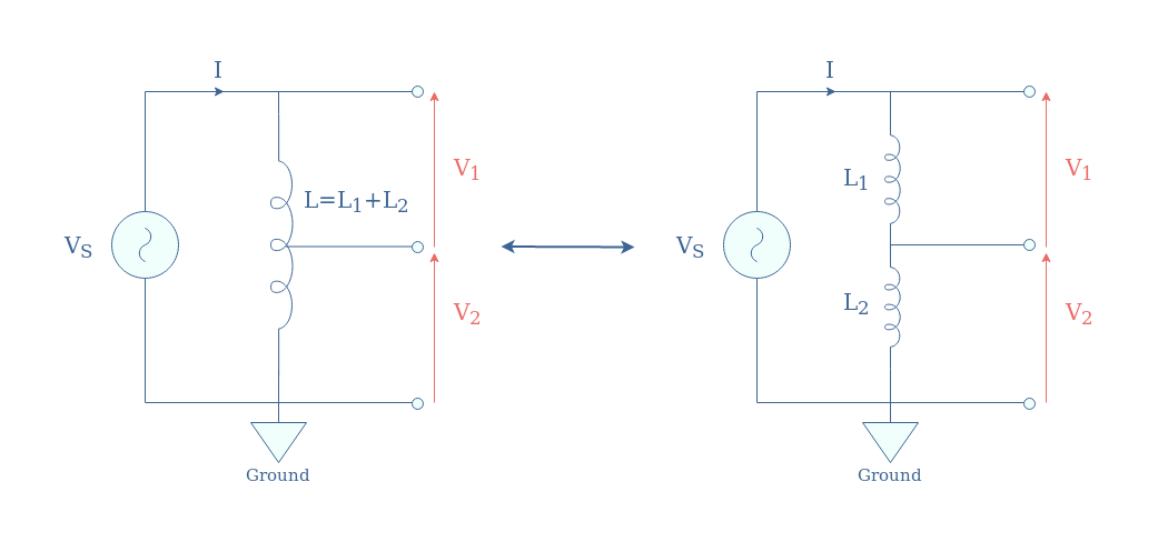
In Figure 8, we present an autotransformer with one intermediary tapping point, which corresponds to the simpler design and is equivalent to two inductances in series:
If we note N1 and N2 the number of windings in L1 and L2, the ratio of voltages is simply given by V2/V1=N2/N1.
Similarly to capacitive voltage dividers, an autotransformer is suitable for high-power applications since the inductors store the energy in the form of a magnetic field and release it to the circuit, producing no heat dissipation.
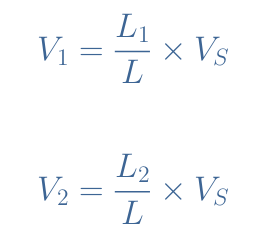
When drawn as an equivalent “inductive voltage divider”, the voltage formulas of the autotransformer are given by Equation 5:
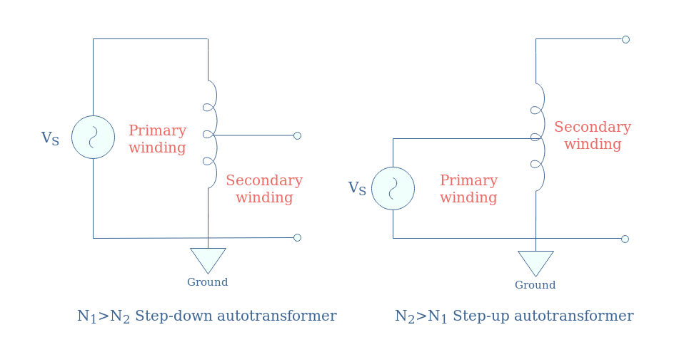
Usually, autotransformers are most found in high-power transmission lines to step-down or up voltages. Step-down and step-up autotransformers are easy to recognize by the proportion of their primary and secondary winding:
Conclusion
Any voltage divider consists of at least two components in a series configuration in which a voltage drop can happen. The output is taken between a tapping point and the reference of the circuit (ground).
The goal of such circuits is to obtain a smaller voltage output value than the source supply VS in order to respect the dynamics of the incoming stage of the circuit. The output corresponds to a fraction of the source, between 0 and VS.
For low-power applications, we rely on resistive voltage dividers based on resistor components. We detail the demonstration of the output voltage formulas, the modification that an output load provides, and the existence of voltage network dividers, where many resistors can be interconnected in series in order to simultaneously provide different voltage outputs.
The disadvantage of resistive voltage dividers is that they are not suitable for high-power applications such as grid distribution. For this function, reactive voltage dividers are preferred as they do not dissipate large amounts of heat such as resistors.
Reactive voltage dividers are divided into two categories: capacitive and inductive, depending on which basic component is used. For capacitive voltage dividers, capacitors are connected in series and the largest voltage drop occurs in the smallest capacitor as their reactance is inversely proportional to their capacitance.
Inductive voltage dividers are most referred to as autotransformers, the largest voltage drop occurs, similarly with resistive voltage dividers, in the largest inductor as their reactance is directly proportional to their inductance.
While capacitive voltage dividers are mostly found in multimeters to probe high voltages, inductive voltage dividers are used in the grid distribution to step-down or step-up 50 Hz high-voltages. A typical example would be that autotransformers establish links between countries that not necessarily use the same voltages in their transmission lines.