Current Dividers
Introduction We have seen in the previous tutorial about Voltage Dividers and that the voltage division process is made possible by associating the same components in a series configuration. In this article, we will focus on the current division process performed by Current Dividers which are parallel associations of components.
Introduction
We have seen in the previous tutorial about Voltage Dividers and that the voltage division process is made possible by associating the same components in a series configuration. In this article, we will focus on the current division process performed by Current Dividers which are parallel associations of components.
The most common type of current divider is discussed in the first section, in its simplest form, it consists of two resistors in parallel.
Some more configurations and details about the resistive current dividers are examined in the second section.
Finally, alternative forms of current dividers partially made with reactive components are presented in the following sections.
Presentation
The most basic resistive current divider configuration is presented in Figure 1 below:
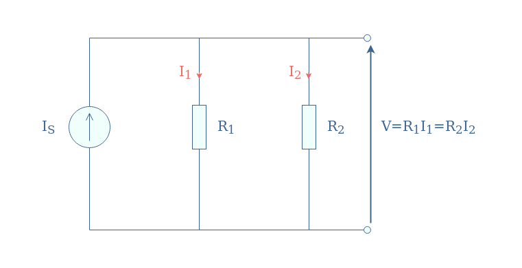
We will now demonstrate the current divider formulas, that is to say, the expressions of I1 and I2 as a function of the source IS and the resistances R1 and R2.
First of all, we express both currents as a function of the voltage V thanks to Ohm’s law: I1=V/R1 and I2=V/R2.
According to Kirchoff’s current law, the current source can be written as the sum of the independent current in each branch: IS=I1+I2=V×(1/R1+1/R2).
Under the same denominator, this expression becomes V=(R1×R2/(R1+R2))×IS. Finally, we replace V in the expressions of I1 and I2 to obtain the resistive current divider formulas:
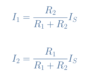
The dimensionless factors in these expressions range from 0 (R2=0 in the expression of I1 or R1=0 for I2) to 1 (R1=0 for I1 and R2=0 for I2) which is interesting to get any possible value of output current from 0 to IS by setting proper values for the resistors.
In practice, the resistance values are never equal to 0 for the simple fact that the resistance of the wires is small but not zero. However, we can still say that for R1>>R2, I1=0 and I2=IS, and for R2>>R1, I1=IS and I2=0.
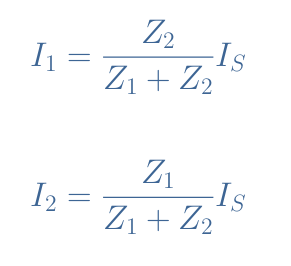
The expressions of Equation 1 can be generalized for any component that constitutes the current dividers, for this, we use the impedance formalization:
Since current dividers consist of associations of components in parallel, it is often recommended to use admittances instead of impedances in order to simplify calculations. Indeed, the admittance of a resistor R is written Y=1/R, and in a parallel configuration, the admittances are simply added up: Ytot=Y1+Y2+…
To illustrate the simplification improvements of this method, we reconsider the circuit in Figure 1 with the admittances:
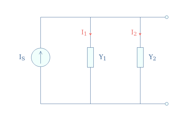
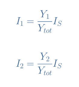
Here, the equivalent parallel admittance is simply given by Ytot=Y1+Y2. Therefore, we have the relation V×Ytot=IS. When replacing V in the expression I1=V/R1=V×Y1 and I2=V/R2=V×Y2, we get the following relations:
A very useful application of current dividers is to safely measure currents while protecting the measuring instrument and user. An example of a current measure is given in the following Figure 3:
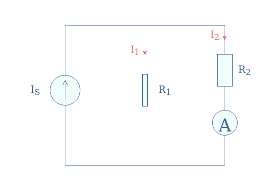
The shape of the components accounts for the proportions that the resistors should take. Indeed, in order to protect the amp meter of high currents, the resistor R2 must be higher than R1 to limit the current across the measuring device.
As an example, if the source provides a current IS=1 A but the amp meter accepts a maximum of 0.05 A, we can choose values for R1 and R2 so that the ratio R1/(R1+R2) is equal or lower than 1/20. The values R1=1 kΩ and R2=19 kΩ would for example satisfy this condition.
Finally, in order to display the correct value to the user, the amp meter simply proceeds to multiplicate the measurement value by the inverse fraction (R1+R2)/R1.
General/network configuration
A general or network current divider configuration is made with more than two resistors in parallel. In the following Figure 4, we illustrate a resistive network current divider with 4 components:
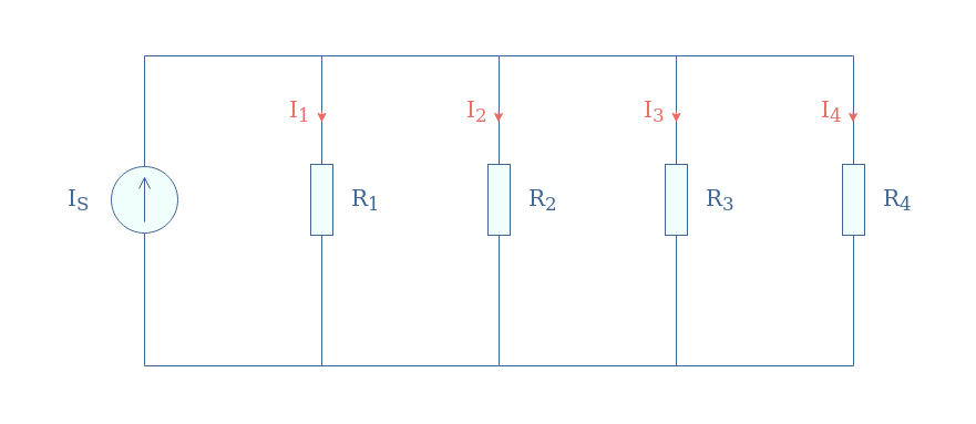
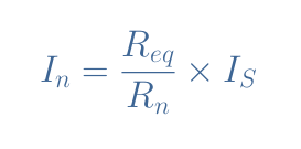
For such a circuit or for any current network divider composed of N resistors, the general formula for any current is given by Equation 4, with Req being the parallel equivalent resistance value.
A current divider network can be used to limit the current in the output, such as presented with the amp meter in Figure 3, but moreover to limit the current in each individual resistor.
As an example, if we reconsider the configuration given in Figure 3 we can compute the power dissipated in each resistor:
- P1=R1×I12=1000×(0.95)2=903 W
- P2=R2×I22=19×103×(0.05)2=47 W
The value of 900 W in the resistor R1 is clearly too much to handle and would melt the resistor structure, even with specially designed high-power application resistors.
With a current divider network, we can split the total amount of power (1000 W) more equally and with lower values in each resistor. We could choose for example to associate 20 resistors in parallel of the same values (1 kΩ). In this case, each resistor would only absorb 0.05 A and dissipate a low-value of 1000×(0.05)2=2.5 W, which respects both conditions of resistors and measuring device protections.
Reactive current dividers
When considering Figure 2, we can replace one of the admittances (say Y2) by a reactive component such as a capacitor or an inductor. These possible associations give interesting properties in the AC regime to the current divider.
Resistor-capacitor current divider
In this configuration, a resistor is placed in parallel with a capacitor such as presented in Figure 5. We refer to this current divider as an R//C association.
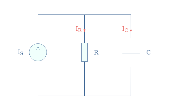
It can be shown that the current across the resistor and capacitor are frequency-dependent and can be expressed by the following relations shown in Equation 5. The current expression of IR is obtained by the generalized current divider formula and the expression of IC by simply applying Kirchoff’s current law.
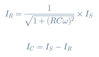
We choose R=1 kΩ, C=5 μF, and IS=1 A in order to show a plot example of these currents:
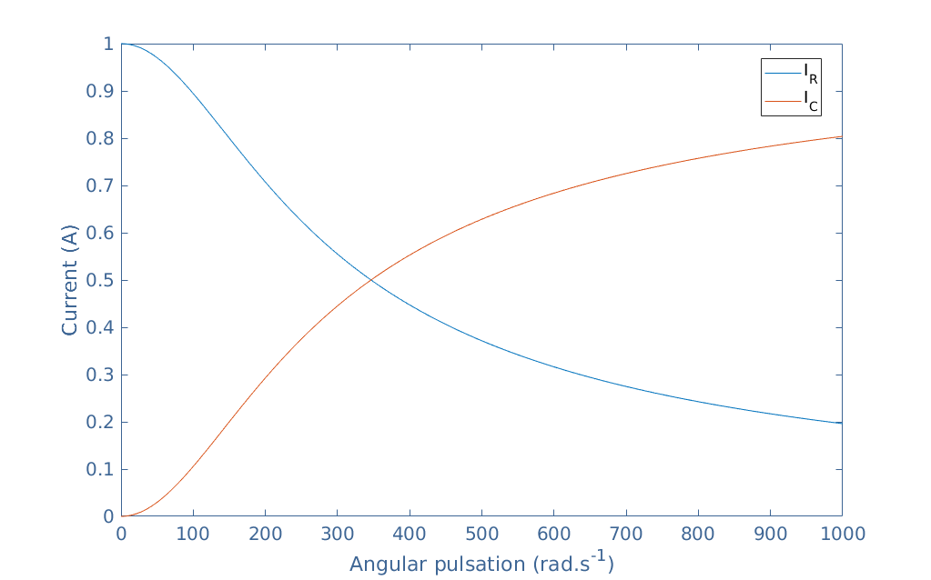
As we can see, due to the reactance of the capacitor, the current IC is zero for low frequencies and increases up to a short-circuit for high-frequencies. On the other hand, the resistor current decreases when the source frequency increases. Note that IR+IC is a constant and equal to IS=1 A.
In practice, R//C circuits are used as low-pass filters in order to cut high frequencies at the output. Moreover, a parallel capacitor is often found in bipolar amplifiers as a coupling and decoupling component in order to shorten to the ground undesirable high-frequency signals.
Resistor-inductor current divider
A complementary circuit to the R//C association can be made thanks to a resistor and inductor placed in parallel that we refer to as R//L association.
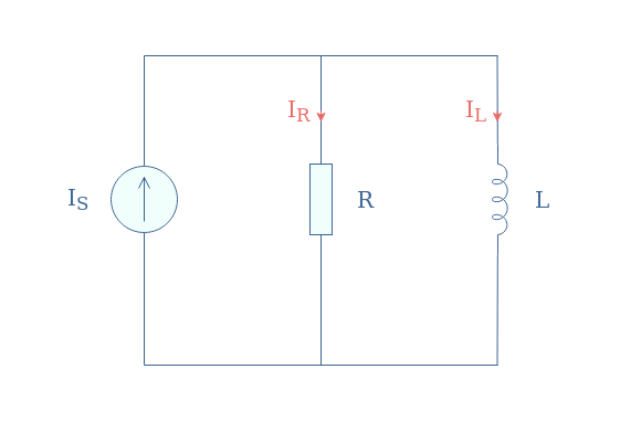
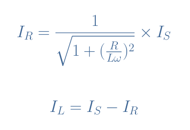
The currents are again dependent on the frequency of the AC source and their expressions are given by Equation 6:
We choose R=1 kΩ, L=5 mF, and IS=1 A in order to show a plot example of these currents:
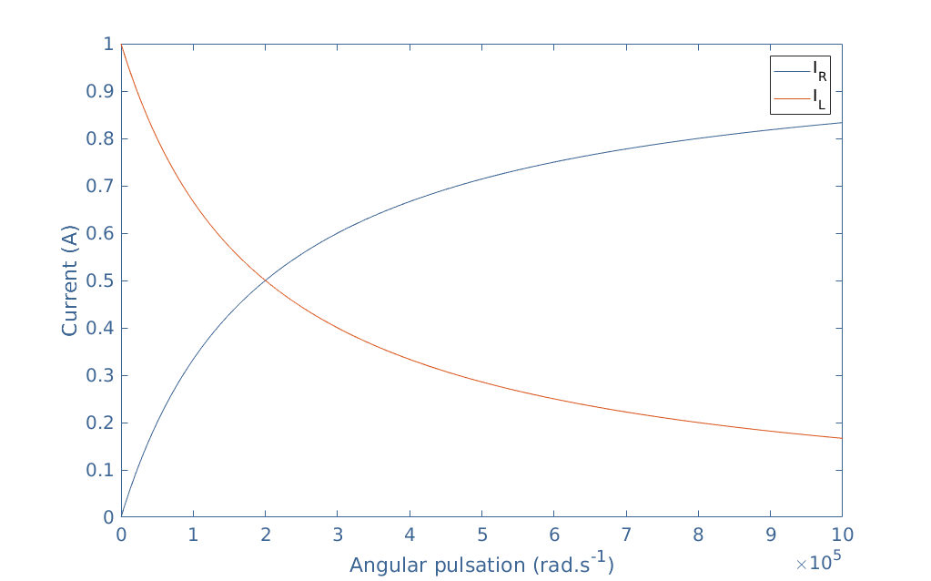
The impedance of the inductor increases with the frequency, as a result, the current IL decreases. When the frequency increases, more current goes across the resistor. Note that IR+IL is a constant equal to IS=1 A.
In practice, R//L current dividers are used as high-pass filters since high frequencies can be collected in the resistor branch. This circuit is the dual of the R//C circuit previously presented.
Conclusion
Current dividers are parallel associations of at least two electronic components that split a current provided by a source into several smaller currents.
Such configurations can provide a good value of current to match the dynamic of any stage in a circuit.
In the first section, we detail the most common and simple current divider that consists of two resistors in parallel. We demonstrate the resistive current divider relations and explain how the circuit works. Moreover, another formalism with the admittances is presented along with a simple example of an application.
Configurations with more than two resistors are presented in the second section, this kind of configuration is useful to split the power into more components and avoid accidents.
Finally, simple current dividers with reactive components are shown in the last section. Due to their frequency-dependent impedances, capacitors, and inductors can be used in parallel with resistors in order to divide the current on some specific range of frequencies.