admin
-
Posts
180 -
Joined
-
Last visited
-
Days Won
5
Content Type
Profiles
Forums
Events
Everything posted by admin
-
This is too generic. Could you be more specific?
-
It seems not publicly available. I couldn't locate it.
-

AC Motor Speed Controller using U2008B to 127 volts
admin replied to Claudemir2019's topic in Projects Q/A
According to the datasheet you can calculate the series resistance R1 using the formula below. This way you can use your desired voltage on the input. I don' t think you need to alter any other component.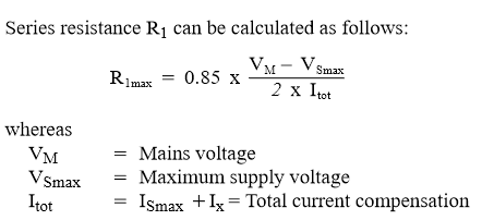
-
Could you give us an idea on the direction you want your topic to be?
-
It is possible to harvest RF energy to power small loads like a small transmitter or bug but i don't think you can charge a mobile phone as it requires much energy. You can check online for "RF energy harvesting", it's an interesting topic to research and there are some special IC build for this purpose. Let us know your findings. 😉
-
Would you like that we feature this on the blog?
-
I would agree, looks like a re-settable fuse to me. Could you measure it in continuity mode to see if it's shorted or not?
-
Designing drawings, 3D, electrical diagrams
admin replied to Openair1985's topic in Sell/Buy electronics - Job offer/requests
Could you provide some samples of your work here? -
They are mostly registering as a plain user, they pass the question, automatic Spam Defense which flags the accounts with spam score and they also approve their email address which is new each time.
-
I have now added: "How many color bands a typical resistor has?", let's see how it goes and if this guessed easily i will replace it.
-
Yes it seems so, any idea for an electronics related question?
-
This feature is enabled on our community but seems spammers get new way to register and post. We keep a close eye on the situation.
-
Which one?
-
Here is another forum topic discussing this power supply. (in Russian) http://forum.cxem.net/index.php?/topic/209045-бп-на-tl081_0-30v-0002-3а-и-его-модификации/ Translated Link: https://translate.google.com/translate?sl=auto&tl=en&u=http%3A%2F%2Fforum.cxem.net%2Findex.php%3F%2Ftopic%2F209045-бп-на-tl081_0-30v-0002-3а-и-его-модификации%2F
-
SeeedStudio is supporting the maker with this great offer! They will assemble your PCB (5 pieces) for free. You just need to purchase the parts and place the order online. More information: https://www.seeedstudio.com/free-assembly-for-5-pcbs.html

-
3D printer's heat bed fabrication (Gerber files)
admin replied to TendtronicB's topic in Electronic Projects Design/Ideas
Thanks for attaching the Gerber. Could you give us more information on the rating (votlage/current) of the heating element as well as why this is needed on 3D printers? -
I need schematic of a 6v 20amps Lead Acid smart Charger
admin replied to Khaleef's topic in Power Electronics
I looked around for such a charger, but seems difficult to find a suitable circuit for such high current output. Let see if someone can come up with a schematic. -
take a look at these 3 phase motor controllers, http://www.electronics-lab.com/project/3-phase-ac-motor-controller/ http://www.electronics-lab.com/project/inteligent-power-module-ipm-board-brushless-motors/ What kind of motor is yours?
-
3D printer's heat bed fabrication (Gerber files)
admin replied to TendtronicB's topic in Electronic Projects Design/Ideas
Could you provide the design files or Gerber files, otherwise this is not usefull for the members of the community. -
Here is the project page: http://www.electronics-lab.com/project/power-supply-brushless-motor-drivers/ This board produces 400V output to power Brushless Servo Drivers, mainly IPM Modules. It is not able to drive the motor. For this purpose you will need a driver board. We can produce this board if order quantity is > 25 pieces. If this interests you, i can quote for that. An Arduino can be used to produce the control signals for the control board.
-
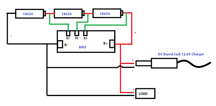
This is the basic connection of BMS charger circuit. Do you need the scheme for the charger it self maybe?
-
power supply 0-30 volt stailized power supply
admin replied to shaknitboss's topic in Electronic Projects Design/Ideas
This power supply is also published on an old Czech electronic magazine attached here. and here is also two nice builds of this PSU: https://translate.google.com/translate?sl=auto&tl=en&u=paja-trb.cz%2Fkonstrukce%2Fzdroj.html and here: http://diyfan.blogspot.com/2012/02/adjustable-lab-power-supply.html 0-30V 3A PSU.pdf -
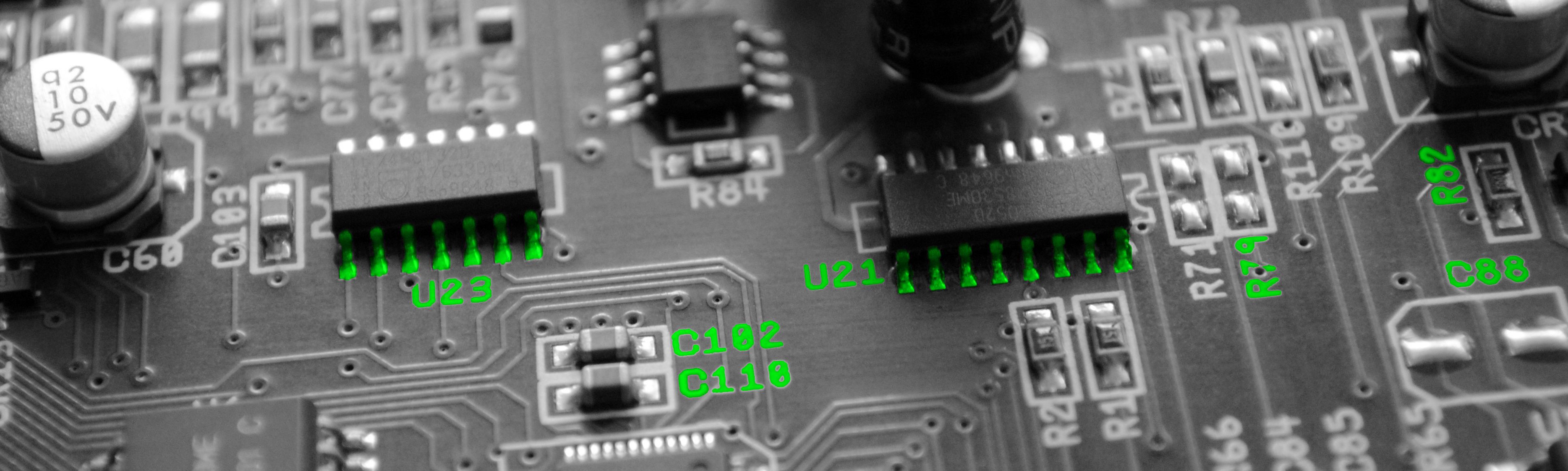
Hi there, These capacitors are filter ones and need to be placed in various spots on the board, near voltage inputs, outputs, IC power pins and other place, so they filter the noise on the Vcc line across the board, so that's why they are many and connected on main voltage. 1n5422 diodes (Schottky diode 40V 2A) are used to protect the ICs from reverse input voltage on their Vin pins, as they allow current to flow in one direction. You can use any Schottky diode with same characteristics. Welcome to our community, Mike
-
This is a popular ESR meter across the web and we also have a revision of it published here: http://www.electronics-lab.com/project/advanced-lc-meter/ Regarding your questions on the first message, let's see if someone who has build it can help out.
-
Can you point us to the most interesting ESR meter you've build?
