

HarryA
-
Posts
451 -
Joined
-
Last visited
-
Days Won
23
Content Type
Profiles
Forums
Events
Everything posted by HarryA
-

need help designing relay circuit
HarryA replied to jim02ss's topic in Electronic Projects Design/Ideas
I would think replacing the relays. You can get a pair of Omron 24 VAC relays for 11$ off Ebay. Omron has a good rating on Amazon.com Else you can use a bridge rectifier to convert to cleaner (less ripple) dc. Search for "bridge rectifier diagram" for many diagrams on the internet. A package with all four diodes in it is about 1$ on Ebay for example. good luck https://www.ebay.com/itm/Relay-Omron-LY2N-J-LY2N-24V-AC-24VAC-COIL-10A-240VAC-28VDC-2-pcs/282975055847?hash=item41e2a0afe7:g:mFAAAOSwlzZbAkIJ -
variable square wave 100 volt 50 amp power supply
HarryA replied to Sedman Smythe's topic in Power Electronics
That sounds like a major project. One would want to use a microcomputer as it would simplify the circuitry greatly. Example: https://www.youtube.com/watch?v=9IWWa0xCd04&feature=emb_logo It is said that power supplies are less expensive today for EDM machines, perhaps you could search on the internet for a good price. I would thing that 2950 pounds is expensive: https://baxedm.com/product/bx17-arc-generator/ I have an eight inch steel disk that I want to make a 100 tooth sprocket from - an electrical discharge machining would be great for that I would think. -
I would think that is a good solution. A more elegant solution would be to use a temperature control switch in series with the fan. They are not very expensive. You want one for example: less than 25 degrees normally open and higher than 25 degrees normally closed. https://www.ebay.com/itm/Temperature-Switch-Control-Sensor-Thermal-Thermostat-25-C-77-F-N-O-KSD301-q-e/333383230245 The admin fixed the ugly url - looks a lot better 😀
-
Motor driver JYQD_7V.3E3 24Volt datasheet (new version)
HarryA replied to Daniel.Karasani's topic in Datasheet/Parts requests
You can download the data sheet from here but it contains little useful information and the diagram is not the correct one. http://www.bldcmotor-driver.com/sale-11494096-500w-brushless-dc-motor-driver-hall-effect-24-volt-dc-motor-speed-controller.html the link is near the bottom of the page. One could buy a board? -
Motor driver JYQD_7V.3E3 24Volt datasheet (new version)
HarryA replied to Daniel.Karasani's topic in Datasheet/Parts requests
By pads do you mean the pads (marked hall) on the lower right of the board? If so knowing any dimension on the board, like a component, one can find other dimensions using a tool like photoshop or the poor man's version THE GIMP. Also knowing the board is 63x42.5x17 mm (L*W*H) one could scale it off the screen. this thing will not go away delete yourself ! Also there is a manual in English here but the link is broken - you may request one perhaps. http://www.brushless-dcmotor.com/sale-11954921-jyqd-v7-3e3-3-phase-brushless-dc-motor-driver-15a-current-pwm-speed-control.html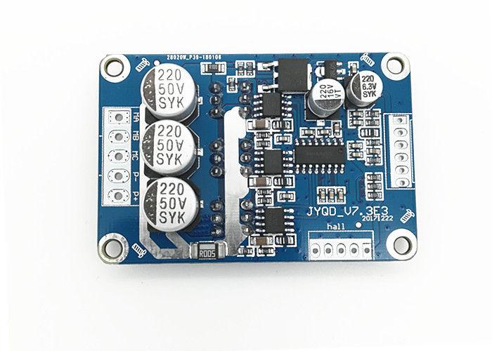
-
Motor driver JYQD_7V.3E3 24Volt datasheet (new version)
HarryA replied to Daniel.Karasani's topic in Datasheet/Parts requests
Searching for: JYQD-V7.3E3 on Yahoo will give you a few hits. Not _7V good luck -
The LMD18200 is rated 3 amperes and 12 to 55 volts: https://www.electronics-lab.com/project/lmd18200-h-bridge-module-for-dc-motor/
-
The IPS6021 is readily available from China via Ebay. There is a supplier in the UK also: https://www.ebay.com/itm/IPS6021RPBF-Intelligent-Power-Switch-High-Side-Active-High-1Output-5-5V-TO-252-5/152755283380?hash=item2390eca5b4:g:U~MAAOSwqXxdNtVK
- 1 reply
-
- 1
-

-
Can you add a heat sink to the transistor - is there enough room for it? A 30 ampere transistor needs a good heat sink bolted to it.. Also you need heat sink compound/paste/grease to get good thermal bonding.
-
There is an old rule that you need at least 2 times the frequency that you wish to view. There is a publication by the ARRL "Oscilloscopes for Radio Amateurs". On Amazon.com is near 20$ used or about 10$ for the kindle version that maybe helpful. The kindle version can be viewed via their free PC app. Also there are videos on YouTube on choosing an oscilloscopes. I have a Hantek DSO5202P it was far more functionality then I need. I did have to replace the display after about three years but they are not expensive. The problem I have is that I answer so many questions that I like to give others a chance to answer some. But that is not always helpful I know. 🤨
-
"Micromicrofarad" or "micro-microfarad" is an obsolete unit found in some older texts and labels, contains a nonstandard metric double prefix. It is exactly equivalent to a picofarad (pF). It is abbreviated μμF, uuF, or (confusingly) "mmf", "MMF", or "MMFD". A microfarad is 10 to the -6 so a micromicrofarad is 10 to the -12 = picofarad from: https://en.wikipedia.org/wiki/Farad Good luck with your radio. I repaired lots of radios years ago. I wish I had some of the old radios I cut up for parts. I still like tubes!
-
Short Circuit protection Using Relay
HarryA replied to rmrps's topic in Electronic Projects Design/Ideas
I would think that when you push the button nothing will happen as the NO (normally open) contacts block the flow of current through the coil of the relay. Are you looking for a 12 volt circuit breaker? Like https://www.ebay.com/itm/12V-24V-DC-HOME-SOLAR-SYSTEM-WATERPROOF-CIRCUIT-BREAKER-RESET-FUSE-INVERTER-USA/153563481272?_trkparms=ispr%3D1&hash=item23c118c4b8:m:mmcjUEQXbNT08tOydOyNxXQ&enc=AQAEAAACUBPxNw%2BVj6nta7CKEs3N0qXpeqhE5Yqs%2B5LvC9kXWBRLunj104AP1sk21at2FZKc2iKh6XL47x1FcO%2BWWY7Rimprmp3h7zN%2FF8RD1a7w7vzGGJeb9L2sR7f6jp3cjblM8ffcC%2FyCeSoSY8lAMKJbUhQ6S8M8LOVbw3gcZrpihnlCk8ERij6l3ii4IEdrt7BTr1HND0HLVDYB85tX0TxWMy4Wq6kO2e4c9S4%2BWinS6pDUakuP3j%2BpaX9BttfII9rjI7xjJnj%2B%2F3fVaA4a9eY03U4A24FUFMwuTrhjRN0WLjdVHVfES9TarXp1Nqr9%2FRtAXJuBcYPC%2FTW7Q4jbkyOcegtOw9dtKtyl9KgHUA6lvz%2FPAcb9QjLahlUE%2BG31z1JrEmfsOmbfmjGGNP0pKGeb9kleHNWuDkMjTGwqsKXQn6yLqiiUhVjtnJ1xTFJKYKD703LIVwIEkfYMIk%2FtNglIpTR%2BzjMcKI6QxGd%2FKD%2FTqOj0lLtOorDfKFUcIeO1%2F0j8LHZO3Yua4YlExNsiHhanZag6MIt5MVTb%2FU4hbfIhgqewz8q06ycP32xVpMz6d4tWdBQN4EKPtPGmU0PnWtCTGZ7aDEuFoPYYG%2FIr5jDaWLGQj30RndKgD7T3H%2FtNskrUCcD7Ypi7UdAOQiNOQ6wvFjlCWz%2BU1X1a4r%2F6ECOOJznNxsK9%2BdtjhS9mbWZcgR7UpoDXiS%2FkqcY1kL9ZVfYgpSoe4z5egyor4y3LYbs1taDt%2B5g84KV8oMwjE6SA60lmeO%2BzHpPjDMrm4SYeGZhi1c0%3D&checksum=15356348127258f693ad8dc343969d0a485f272220a5&enc=AQAEAAACUBPxNw%2BVj6nta7CKEs3N0qXpeqhE5Yqs%2B5LvC9kXWBRLunj104AP1sk21at2FZKc2iKh6XL47x1FcO%2BWWY7Rimprmp3h7zN%2FF8RD1a7w7vzGGJeb9L2sR7f6jp3cjblM8ffcC%2FyCeSoSY8lAMKJbUhQ6S8M8LOVbw3gcZrpihnlCk8ERij6l3ii4IEdrt7BTr1HND0HLVDYB85tX0TxWMy4Wq6kO2e4c9S4%2BWinS6pDUakuP3j%2BpaX9BttfII9rjI7xjJnj%2B%2F3fVaA4a9eY03U4A24FUFMwuTrhjRN0WLjdVHVfES9TarXp1Nqr9%2FRtAXJuBcYPC%2FTW7Q4jbkyOcegtOw9dtKtyl9KgHUA6lvz%2FPAcb9QjLahlUE%2BG31z1JrEmfsOmbfmjGGNP0pKGeb9kleHNWuDkMjTGwqsKXQn6yLqiiUhVjtnJ1xTFJKYKD703LIVwIEkfYMIk%2FtNglIpTR%2BzjMcKI6QxGd%2FKD%2FTqOj0lLtOorDfKFUcIeO1%2F0j8LHZO3Yua4YlExNsiHhanZag6MIt5MVTb%2FU4hbfIhgqewz8q06ycP32xVpMz6d4tWdBQN4EKPtPGmU0PnWtCTGZ7aDEuFoPYYG%2FIr5jDaWLGQj30RndKgD7T3H%2FtNskrUCcD7Ypi7UdAOQiNOQ6wvFjlCWz%2BU1X1a4r%2F6ECOOJznNxsK9%2BdtjhS9mbWZcgR7UpoDXiS%2FkqcY1kL9ZVfYgpSoe4z5egyor4y3LYbs1taDt%2B5g84KV8oMwjE6SA60lmeO%2BzHpPjDMrm4SYeGZhi1c0%3D&checksum=15356348127258f693ad8dc343969d0a485f272220a5 You don't see a URL like that everyday! You could put a relay across it with a single pole double throw contacts so that when there is not short you light a green led else a red one. How to build a circuit breaker is shown here that could be modified for 12 volt operation if that is your goal. https://www.brighthubengineering.com/diy-electronics-devices/74420-make-an-ac-mains-electronic-circuit-breaker/ Else define what your goal is better. Good luck. -
Capacitor conversion chart / table - a capacitor value conversion chart or capacitor conversion table to convert capacitor values between picofarads (pF), nanofarads (nF), microfarads (µF) Capacitor Conversion Chart microfarads (µF) Nanofarads (nF) Picofarads (pF) 0.000001 0.001 1 0.00001 0.01 10 0.0001 0.1 100 0.001 1 1000 0.01 10 10000 240 pf capacitors are available on ebay
-
From above: Hello, first of all they call me José Silva, (FRISIL). I just registered at Comunidad Electronics-Lab.com. I am not a professional in electronics, I am just beginning and with advanced age (55 years). I have been watching the development of this source and it has aroused great interest in putting it together. I am simulating it in proteus with TL081, I have a question about SetOFF NULL in U2. Does this potentiometer go between pin 1 and 5? https://translate.google.com/
-
TDA8512J, any other part that can replace this one ?
HarryA replied to El Medin Nukovic's topic in Power Electronics
At the bottom of this page is a TDA7387EPAG that you could look at. Plus 53 more pages! https://www.mouser.com/Search/Refine?N=7508787+4292906361&FS=True Good luck. -
A search on the internet will yield numerous sites with information on class AB power amplifiers. Like: https://www.electronics-tutorials.ws/amplifier/class-ab-amplifier.html That method of implementing a class D amplifier is beyond me.
-
Most likely there is a shot within the transformer windings. You may be able to unwind some of the wire and find the shorted section and repair it. Search for transformer windings on YouTube for insight into transformers. Like: https://www.youtube.com/watch?v=mXFuVHkY8aA for example.
-
That seems like a good idea. I gather that such refrigerators draw something like 5 to 7 amperes. A relay could handle that; such as: https://www.ebay.com/itm/NEW-Philips-ECG-RLY1522-12-Volt-DC-Coil-10-Amp-SPDT-General-Purpose-Relay/251877100313?epid=2282812589&hash=item3aa50b8b19:g:qVsAAOSw7ZFVAh~t I think one should put a diode across the relay coil (in reverse) to protect the controller.
-
If you search on amazon.com for "arduino rf" you will find various transmitter - receiver options. Like this for example> https://www.amazon.com/WHDTS-Transmitter-Receiver-Transceiver-Communication/dp/B07L8RXSDF/ref=sr_1_36?keywords=arduino+rf&link_code=qs&qid=1574902183&sourceid=Mozilla-search&sr=8-36 for this model note: T400 Transmission Distance: 400M T400 Receiving Distance: 50M GWB Transmission Distance: 400M GWB Receiving Distance: 400M I do not see the differences between the T400 and the GWB units when ordering the units.
-
Congratulations! Looks like you got read of the bad guys 😊
-
Ideas for low quiescent current high voltage charging circuit
HarryA replied to Baphomet12's topic in High Voltage Stuff
Consider using this: "DC-DC Converter 3V-5V Output Step Up Step down Buck Boost 300V-1200V PSU Module" https://www.ebay.com/itm/DC-DC-Converter-3V-5V-Output-Step-Up-Step-down-Buck-Boost-300V-1200V-PSU-Module/264035829269?_trkparms=aid%3D1110001%26algo%3DSPLICE.SIM%26ao%3D1%26asc%3D20131231084308%26meid%3D303593509b5d4479a35466a0cb15c884%26pid%3D100010%26rk%3D11%26rkt%3D12%26sd%3D174073965556%26itm%3D264035829269%26pmt%3D1%26noa%3D1%26pg%3D2047675&_trksid=p2047675.c100010.m2109 If one monitored the capacitor voltage so when it got charged the battery was switched off and back on when it got low the average current drain on the battery would be acceptable perhaps. One could use JFETs and large (mega-ohm resistors) so the drain would be low on the capacitor. The converter would be switched on and off as it charged and recharged the capacitor; so the average current draw would be acceptable. Someone who knows JFETs better than I would be helpful here. -
Need help with using a transistor or triac as a switch
HarryA replied to MAJ's topic in Projects Q/A
Lets see if this is readable. Using a 2n2222 - about 10 cents apiece. Current from the source is 40ma with a base resistor of 1000 or 10k. In the view the yellow trace is the current through the relay; scale on the right . Green is the voltage at the base; scale on the left. I have no idea what the inductance would be so I set it at 0.001 henry.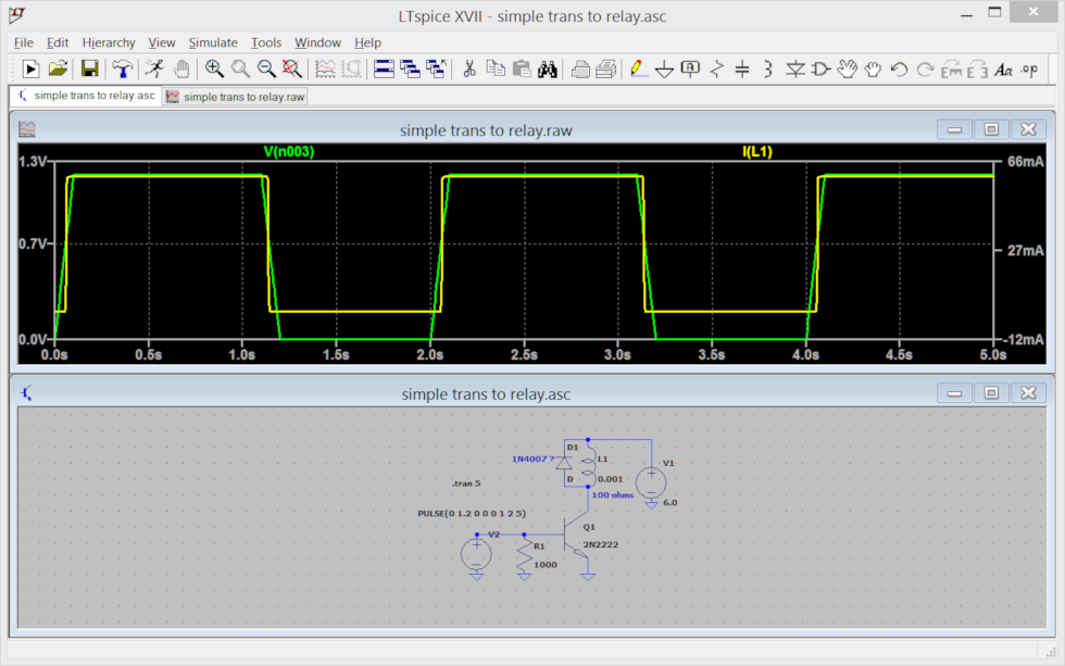
-
About the "50V – 10A BIDIRECTIONAL DC MOTOR DRIVER USING A3941" issue
HarryA replied to kmimax's topic in Projects Q/A
from: http://static6.arrow.com/aropdfconversion/ee14f7b4a3764f5a2d5bf5d73381b76d11c173d/3a3941-datasheet.pdf.pdf
-
Circuito (Medición de variables)
HarryA replied to Emanuel Celis Cano's topic in Spice Simulation - PCB design
Medición de variables electricas modelo #2 (Measurement of electric variables model # 2) ¿Qué es el modelo # 2? (What is model #2 ?) -
I believe your circuit is not quite correct. The resistor and capacitor (C1 and R3 ?) belong to the DIAC not the TRIAC. see the circuit here: https://www.electronicshub.org/simple-fan-regulator-circuit/