HarryA
-
Posts
453 -
Joined
-
Last visited
-
Days Won
24
Content Type
Profiles
Forums
Events
Everything posted by HarryA
-

Buck Converter Design
HarryA replied to ElectronicsLabUser's topic in Electronic Projects Design/Ideas
There is a lot to designing a dc to dc buck converter. For example see: https://www.maximintegrated.com/en/design/technical-documents/tutorials/2/2031.html You can buy one for far less than the cost of the parts to build one. See: https://www.amazon.com/Aceirmc-Converter-Adjustable-Regulator-Protection/dp/B0823MM1DV/ref=sr_1_6?crid=1AB7YZ4O9O8B0 You may find complete circuits on the internet. The inductor is the tricky part . What to use as a core and how to wind it for 20 amperes. -
"My inverter is not same to the real inverter working principle" What does your inverter look like? Schematic diagram? "Is there anyone suggest me a diagram for inverter" What type of inverter are your trying to build? Are you looking for 12 volts dc to 120/220 volts ac for example?
-
"scan picc to see uid, sak, type, and data blocks." huh? The mfrc522 supports three interfaces: • Serial Peripheral Interface (SPI) • Serial UART (similar to RS232 with voltage levels dependant on pin voltage supply) • I2C-bus interface Which one are you using? What software are you using?
-
Here are a couple of circuits that maybe helpful: https://www.homemade-circuits.com/dog-barking-preventer-circuit/#:~:text=Referring to the above shown dog bark inhibitor,using the IC2 and the speaker driver stage. and: https://www.electroschematics.com/dog-repellent-circuit/ Perhaps a piezoelectric transducer would be louder than a speaker. Would require a different driver circuit. I used a device that women carry for protection that contains a piezoelectric transducer in my cat detector. That is in the lower audio range of cause. It's very loud. I gather they work well in the ultrasonic range as they are used in ultrasonic cleaners.
-
Pack of 5, T630mA250V, T630mA 250V, T630m 250V Cartridge Ceramic Fuses 5X20mm see for example: https://www.ebay.com/itm/151136254075?chn=ps&norover=1&mkevt=1&mkrid=711-213727-13078-0 T for time delay? From Amazon.com: Pack of 5, T630mAL250V, T630mA 250V, T630mL250V Cartridge Glass Fuses 5X20mm (3/16" X 3/4"), 630mA 250V, Slow-Blow (Time Delay)
-
Looking on Ebay you see G04N60 from China. Not much help. Searching on A1F02LSIN takes you to this site; not very helpful but more interesting. https://www.barenecessities.com/product.aspx?pfid=Empreinte07151&cm_mmc=BPLA_NonBrand-_-Bra-_-Empreinte422-_-Empreinte07151&
-
Tablet charging IC replacement
HarryA replied to Vasant Seechurn's topic in Datasheet/Parts requests
Do you think it is a D6Gi1K or D6GiLK ? After the G it looks like an aye i gather. Not even close: http://twitpic.com/d6gilk SOT323 is a SMD package type; it has only three leads. Often a transistor. -
One problem about building an electronic level with Arduino
HarryA replied to Holy Hathaway's topic in Electronics chit chat
I have for sometime now been dorking around with the MPU6050. I started out using Joop Brokking's code for a quadcopter but put it aside to educate myself on the PID software and the MPU6050 software. As you say there always seems to be problems with the MPU6060 code running away - the output of the formatted code seems to increase without limit. I am working with Joop Brokking's balancing beam code with and without the motors he uses to demonstrate using the MPU6050 and using the PID control software. That has the same problems. I migrated to Dejan_code.ino code because of its simplicity. That has stable 'raw' outputs of the MPU6050. And is well behaved; in that if you rotate the MPU6050 to some angle it shows some stable raw value and returns to the zeroed values on rotating it back to zero angle. The values around zero angle only vary by plus or minus 10 or less - I call that stable. That code contains a calibration functions that displays the values required to correct the raw outputs to near zero. These values are used later within the code for corrections. Manually updated. I am currently using this code to understand why the formatted code output is unstable by displaying the values at various stages in the program. I also looked the Digital_Level_v1.ino code (the yellow level) but had problems getting it to compile. I get an error "no 'uint8_t MPU6050_Base::dmpInitialize()' member function declared in class 'MPU6050_Base'" related to the MPU5060_6axis_MotionApp20.h file. This code is just to complex for me at this stage for what I want to do. The Dejan_code.ino code is perhaps the beat code to learn about the MPU6050 from. No PID! https://howtomechatronics.com/tutorials/arduino/arduino-and-mpu6050-accelerometer-and-gyroscope-tutorial/ -
SQ2LA appears in these two by Google advance search but I could not find any info at the web site: http://www.smdmark.com/en-US/ic-492522.html
-
Looking for a board that can send email when tripped on WiFi
HarryA replied to DigitalHillbilly's topic in Electronic Gadgets
You may find the ESP8266 WiFi transceiver interesting: https://circuitdigest.com/microcontroller-projects/getting-started-with-esp8266-module -
Looking for a board that can send email when tripped on WiFi
HarryA replied to DigitalHillbilly's topic in Electronic Gadgets
Sorry I can not help you. I would be challenged doing it with a microcontroller: https://arduinogetstarted.com/tutorials/arduino-send-email -
Through-Beam Photoelectric Beam Sensor
HarryA replied to saveearth123's topic in Electronics chit chat
I used a infrared transistor as a detector and diode emitter to make measurements on my quadcopter by having the blade pass through a gap with one on each side. You can get similar optical detector devices already mounted in pairs and separate them I would think. See this one for example: https://www.ebay.com/itm/402866611861?hash=item5dccb8a695:g:uUEAAOSwby1gql8L or unmounted: https://www.ebay.com/itm/274298671466?hash=item3fdd79916a:g:j~YAAOSwWNNdp9Dl The data sheet with circuit can be found here: https://www.digikey.com/en/products/detail/omron-electronics-inc-emc-div/EE-SG3/31139?s=N4IgTCBcDaIAQHkBKBWADAFgLQDkAiIAugL5A Perhaps an enclosure like this?
-
Circuit to increase CEMF spikes
HarryA replied to Kerrowman's topic in Electronic Projects Design/Ideas
It is some where in here: So a henry = an ohm per hertz? see: https://en.wikipedia.org/wiki/Henry_(unit) See the RL calculator here: http://learningaboutelectronics.com/Articles/RC-RL-time-constant-calculator.php#answer2 I will try it in the tina-ti simulator - we have a mutual dislike for each other!
-
Circuit to increase CEMF spikes
HarryA replied to Kerrowman's topic in Electronic Projects Design/Ideas
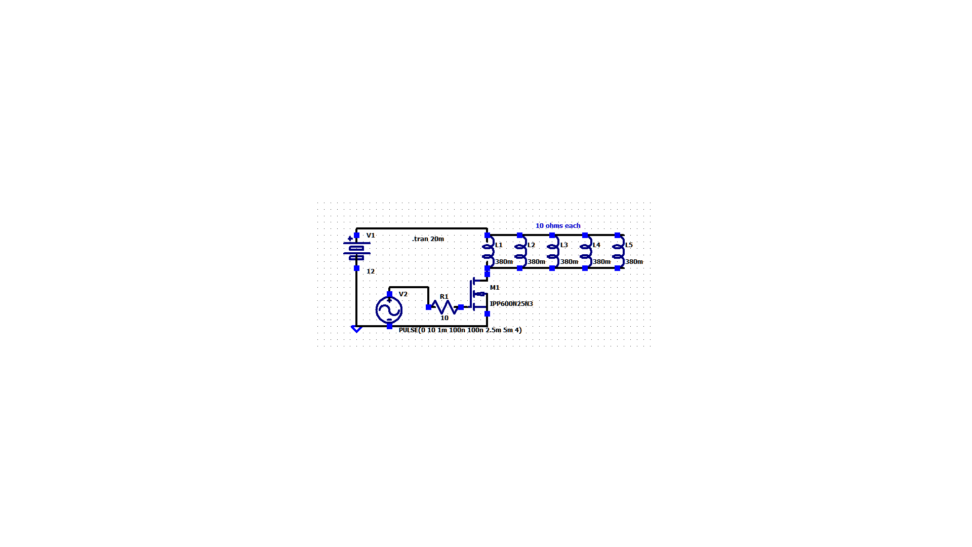
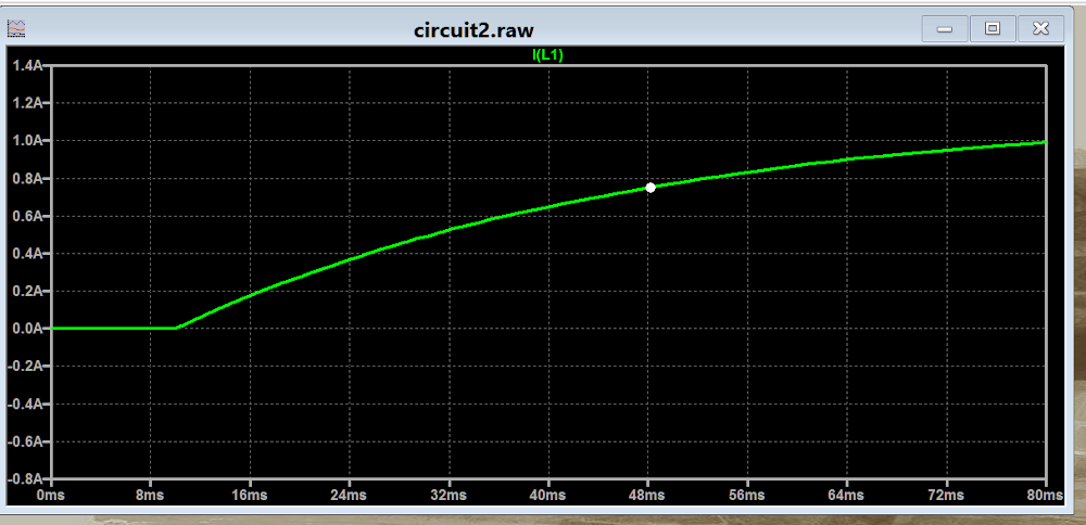
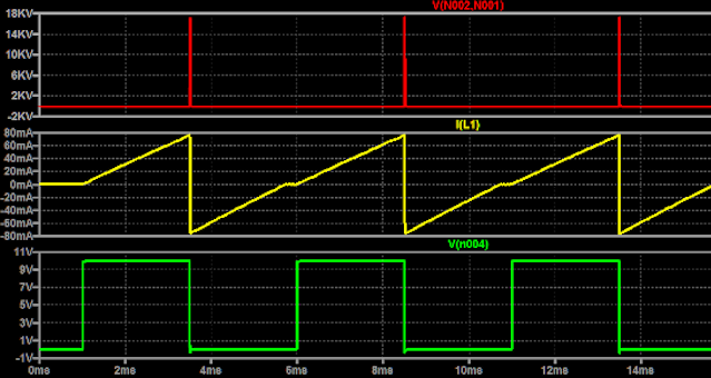
It takes in the order of 200ms for the current to reach maximum in the simulator. The current through one coil is about 1.18 amperes. The voltage across the coils is about 200kv - you better wear rubber boots! Perhaps the simulator got carried away. There is an equation: time = inductance/resistance = 63% of the charge. So t= 0.380h /10 ohms would give 38ms. That would give 0.74amps at 48ms (38ms + 10ms pulse on delay) in the second waveform. That seems about right; at the white dot.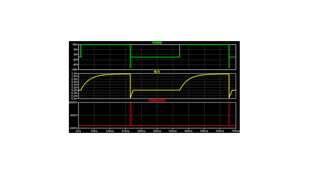
-
Circuit to increase CEMF spikes
HarryA replied to Kerrowman's topic in Electronic Projects Design/Ideas
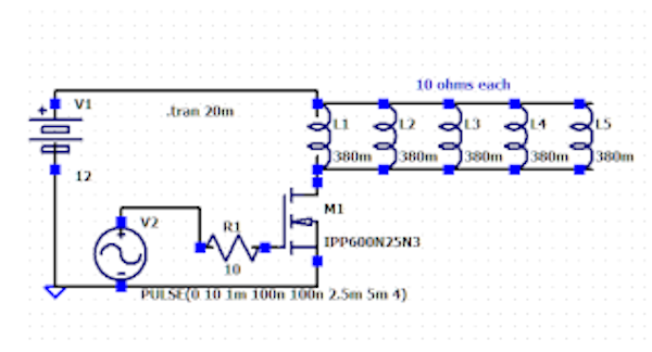
Using the circuit below with an 2.5ms wide pulse at 10v with rise and fall times of 100ns in the simulator I get the wave forms below. The green trace is the input at the base of the mosfet, the yellow trace is the current through one of the coils while the red trace is the voltage across the coils. I will try increasing the pulse width until the current reaches steady state and see what is looks like and post it later. I do not understand the current.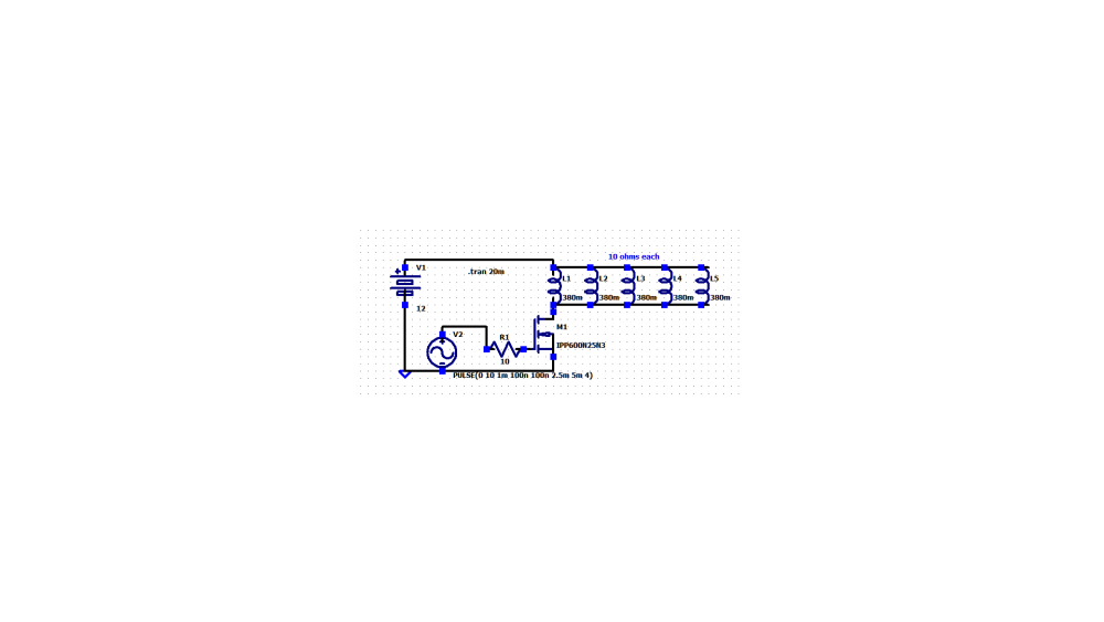
-
Circuit to increase CEMF spikes
HarryA replied to Kerrowman's topic in Electronic Projects Design/Ideas
Looks impressive! Do you have an idea of the inductance of the coils? I could play with it in the simulator. -
Circuit to increase CEMF spikes
HarryA replied to Kerrowman's topic in Electronic Projects Design/Ideas
Is the pulse width large enough for the coil current to reach maximum? I would think current should get to something like (12v - mosfet saturation voltage)/Rcoil. Also the break down voltage of the mosfet and its diode may come in to play at high voltages? for others:
-
Circuit to increase CEMF spikes
HarryA replied to Kerrowman's topic in Electronic Projects Design/Ideas
I am not sure about their graph either. You could try playing around with a capacitor but I am not sure how much it affects the voltage drop rate at the output. As you are 95% there why not use an electronic ignition circuit? There are numerous circuits like this one on the internet. You could get up to a few thousand volts then!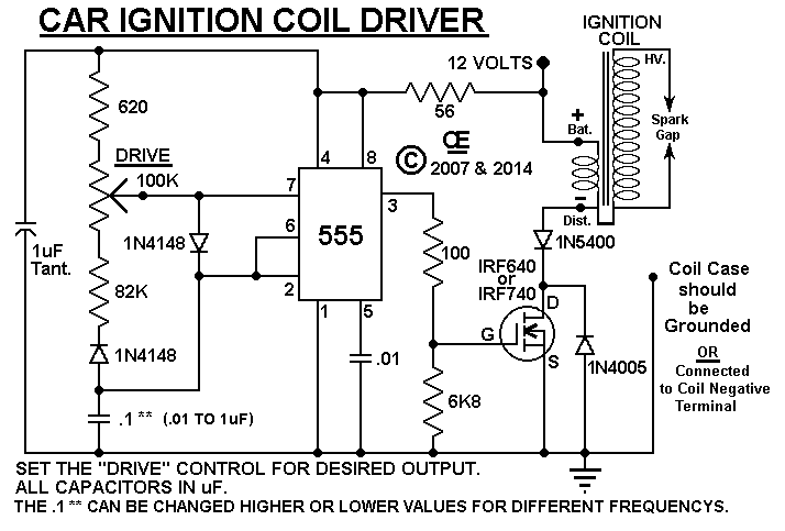
-
Circuit to increase CEMF spikes
HarryA replied to Kerrowman's topic in Electronic Projects Design/Ideas
Yes, as in the above link. -
Circuit to increase CEMF spikes
HarryA replied to Kerrowman's topic in Electronic Projects Design/Ideas
They often use a diode across your R5, I gather to discharge the gate capacitor to speed it up. See this link and click on the "simulate transient" for the IPP60R099CP. https://design.infineon.com/tinademo/designer.php?path=EXAMPLESROOT|INFINEON|Applications|Industrial|Power|&file=power_MOSFET_compare_450V.tsc&act=change.U.Infineon.IPP60R099CP_L0 I wonder if the turn off delay of the 555 propagates through the circuit? The 555 off time is 2us compared to the equivalent timer 1455 at 100ns. -
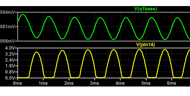
Help please with this 4017 Kit
HarryA replied to Yoda Man's topic in Electronic Projects Design/Ideas
I gather you are using the output from your speaker as input rather than a microphone. In the simulator I get, with zero signal, about 580mv dc at the transistor base and 600mv dc output (pin14). Using 1k sine wave at 10mv as input I get, at the transistor base, a signal between say 670 - 690mv, At the output pin14 0 to 3.5v. Using a 2SC2412K in the simulator which I believe is similar to the 9014.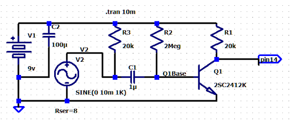
-
Questions about replacing the speaker
HarryA replied to Holy Hathaway's topic in Electronics chit chat
I gather you are employed by Kynix. 🤑 For others: That would be a very large impedance mismatch. The speaker impedance is 4 to 8 ohms while the impedance into the PC is in order of 1k to 20k ohms. -
TDA7498 class D amp could be used as a substitute?
HarryA replied to Holy Hathaway's topic in General
How do you deal with a SMD that has 36 leads? -
need help electronic/relay problem phone horn
HarryA replied to georgebaker's topic in Electronic Projects Design/Ideas
As you have posted this question on numerous forums I will leave it up to them to answer your question. Good luck. -
These motor controllers may interest you: Motor control Info on Youtube here: Review of control And more info here: More motor control. Reading the reviews/comments will give you more insight. Could one mount the potentiometers into a joystick control mechanically; some type of gimbal mount? Adding push button switches to the control to reverse directions would be doable I think. There maybe game type joystick controls that have them already built in?