

Current Sources
- Boris Poupet
- bpoupet@hotmail.fr
- 12 min
- 4.360 Views
- 0 Comments
- 0 Likes

Introduction
In the continuity of the Voltage Sources tutorial, we present in this article the Current Sources, which are the second type of electric sources we will look at.
Similarly to what has been done for the voltage sources, we will first introduce the concept of ideal current sources where their particularities and characteristics are discussed.
In real circuits, however, ideal current sources cannot be found as some paradox and impossibilities appear with this model. We distinguish these practical sources as real current sources and we will see what are their differences with the ideal model. The interconnection rules between two or several current sources are also discussed further in the same section.
Finally, the last section details the dependent current sources which are voltage or current-controlled current sources.
Presentation
An ideal current source is a device that can supply a constant and stable value of current regardless of the voltage that must be provided to a specific output load. The ideal current sources are represented by a double circle or an arrow within a circle such as illustrated in Figure 1 below:
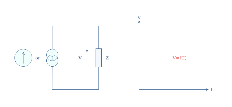
The characteristic of an ideal current source is sometimes represented I=f(V) as the representation above in Figure 1 is, strictly mathematically speaking, not a function but a distribution.
Real current sources
The internal power losses that take place in a current source can be modelized by a resistor (RS) associated in parallel. The I/V characteristic is not anymore flat but, such as for voltage sources, is corrected with a slope of value -1/Rs such as illustrated in Figure 2:
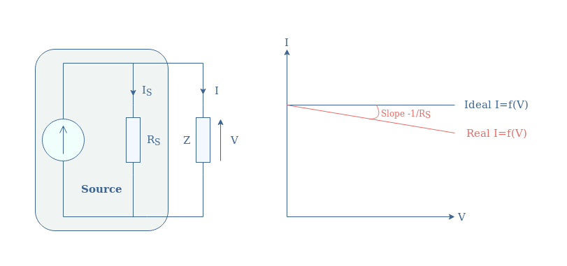
We can note that an ideal current source is equivalent to a real source which resistance RS tends to +∞ (open circuit).
Connection rules
In this subsection, we highlight the fact that some connection rules are necessary to keep in mind when integrating current sources in a circuit.
First of all, the terminals of a current source must not be placed in an open circuit:
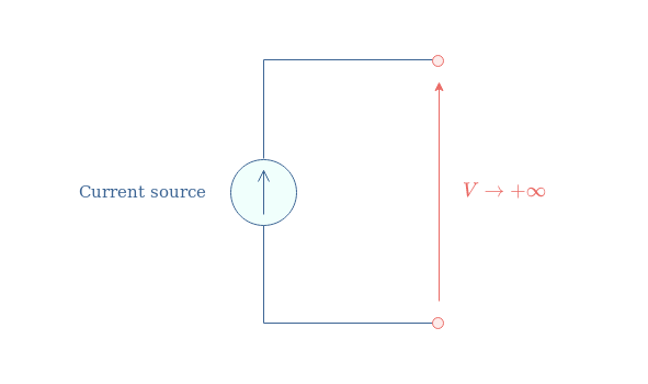
The resistance of an open circuit is +∞, when the source provides a current that is not equal to zero, the voltage quantity tends to +∞, which is not possible. In practice, the voltage will increase until its breakdown value, forcing the air/vacuum between the source terminals to become conductive. This phenomenon often leads to the destruction of the source or at least one of its components.
Moreover, the series connection of two or many current sources is also proscribed, even if both sources supply the same current value.
The reason why this type of connection is not allowed is that an equivalent circuit cannot be predicted: will the sources add, or only one will effectively work?
The current in a branch of a circuit can only take one value, there cannot be an overlay of many currents.
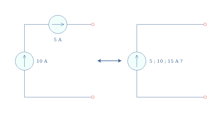
Finally, the parallel association of current sources is absolutely allowed and recommended to obtain a higher output current:

As shown in the second circuit in Figure 5, the values can also be subtracted if one of the sources is oriented in the opposite direction.
In a parallel configuration, the output current is the algebraic sum of the current sources involved in the supply process.
Dependent sources
In the previous sections, an independent current source has been presented and their value is fixed and depends only on the source’s design.
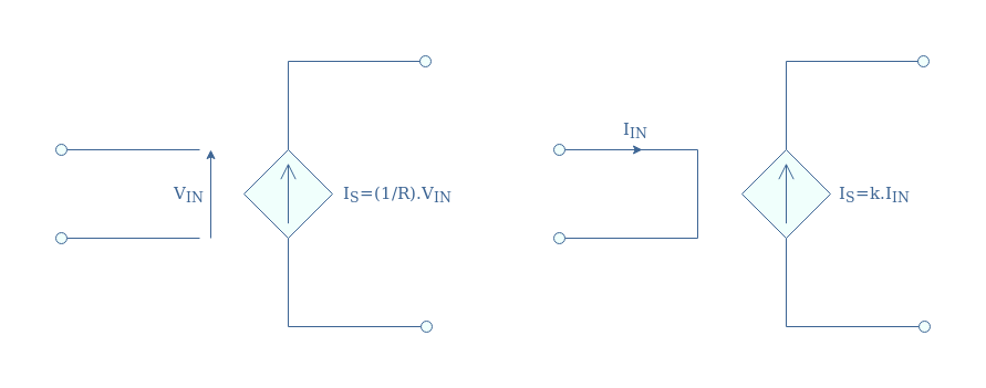
The current value of dependent current sources can be tuned with an external parameter. There are two types of dependent current sources: Voltage Controlled Current Sources (VCCS) and Current Controlled Current Sources (CCCS). In a circuit diagram, current dependent sources are symbolized by an arrow shape (in the direction of the current) surrounded by a diamond pattern:
Voltage Controlled Current Source
For this type of dependent current source, the nature of the input (voltage) is different than the output (current), the linking factor is labeled σ=1/R and represents a conductivity in Siemens (S) or Ω-1.
We illustrate what a simple circuit containing a VCCS can look like in Figure 7 and show how to compute its input.
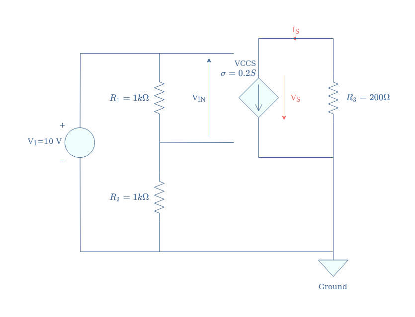
Since the voltage source V1 supplies a voltage divider 1 kΩ/1 kΩ, the input of VCCS is given by VIN=V1/2=5 V. Since the gain of the VCCS is 0.2 S, the output current of the dependent source is IS=0.2×VIN=1 A. The output voltage is simply computed by applying Ohm’s law to the resistor R3, we obtain VS=IS×R3=200 V.
An example of VCCS is the MOSFET amplifier which is a voltage-effect-based transistor:
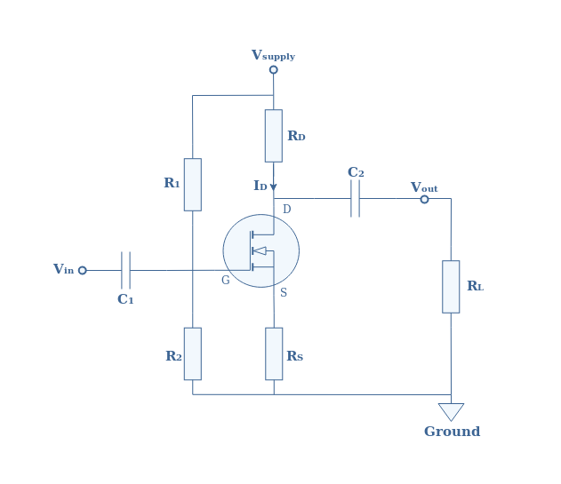
As a VCCS, the MOSFET amplifier takes as input a voltage known as gate voltage and delivers an output current known as drain current.
We can affirm that a MOSFET is indeed a current source after looking at its characteristic ID=f(VDS):
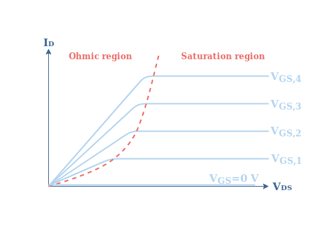
Depending on the command gate voltage (VGS), the characteristic of the MOSFET amplifier becomes flat after a certain value of the output voltage VDS. This characteristic in the saturation region is typical for a current source.
Current Controlled Current Source
In the case of CCCS, both the input and output are of the same nature (currents), the gain is, therefore, a dimensionless quantity labeled k.
We illustrate again a similar circuit that integrates a CCCS in order to clarify how to retrieve the output quantities:
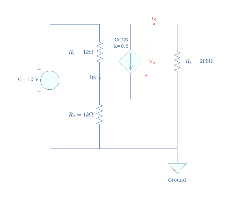
The input current controlling the CCCS is here given directly by Ohm’s law: IIN=V1/(R1+R2)=5 mA. The output current is obtained by multiplying the input current by the gain k, IS=k.IIN=3 mA. Finally, the output voltage is again given by applying Ohm’s law to the resistor R3, VS=IS×R3=0.6 V.
Examples of CCCS are bipolar junction transistors (BJT)-based amplifiers, the reader can refer to the tutorials about Common Emitter Amplifier and Common Collector Amplifier in order to get more details.
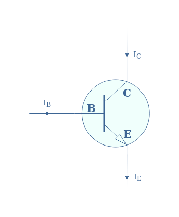
Figure 11 is a plot of the output characteristic in the collector branch (C) for several command base currents (IB):
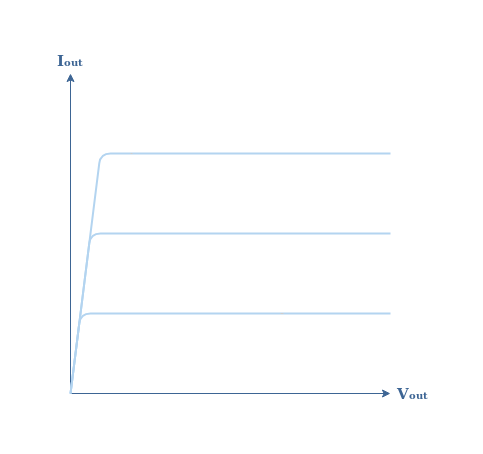
We recognize again a flat I/V function after a certain value of voltage, typical for a current source, exactly such as for the MOSFET amplifier.
Conclusion
In order to conceptualize current sources, we have first presented ideal current sources that are not real devices but rather an ideal construction. Ideal current sources provide a constant and stable output current value regardless of the value of the voltage across the output load. They are identified by a flat I/V characteristic which presumes than an infinite amount of power can be provided.
Real current sources, however, present a light slope in their I/V characteristic in order to account for the internal power losses. The value of this slope is given by the conductivity of the source resistance placed in parallel with the source. The source resistance is not physically present in the device but it is rather a way to explain and simplify the calculations.
Moreover, we have seen that some connection rules must be taken into account when designing circuits that include current sources. Placing the current source in an open circuit and associating in seres two or more sources is not recommended. The parallel association is, however, acceptable since it is a useful technique that can increase the output current.
Finally, we have seen that some special current sources can be controlled by an external quantity of the circuit. They are known as dependent sources and for current sources, two types exist:
- Voltage Controlled Current Sources (VCCS)
- Current Controlled Current Sources (CCCS)
Typical examples of current dependent sources are MOSFETs (VCCS) and BJT transistors (CCCS).
Please follow and like us:
Subscribe
Login
0 Comments


