OPAMP Comparators
Introduction In most of the previous operational amplifier tutorials, the circuits had a feedback loop to the inverting input. This design is the most common because it provides indeed stability and avoids undesirable saturating effects and, it is also common to call it the linear mode.
Introduction
In most of the previous operational amplifier tutorials, the circuits had a feedback loop to the inverting input. This design is the most common because it provides indeed stability and avoids undesirable saturating effects and, it is also common to call it the linear mode.
On the other hand, when no feedback is applied to the inverting input, the op-amp is said to work in the non-linear regime, we can also say in an open-loop configuration. Comparators are specific op-amps circuits that are meant to work in a non-linear mode and can be used as simple logic gates.
A presentation of the circuit along with the basics about comparators is given in the first section.
In the second section, we increase the complexity of the circuit in order to show how to translate the so-called “tipping point” or “threshold” of the comparator. We show that being able to translate this value is important in order to properly design level detectors.
Schmitt triggers are discussed in a third paragraph, we will see how this kind of comparators work and how they can be used in real applications. Moreover, we highlight their advantages by comparing them to basic comparators.
Presentation
Non-inverting comparator
The simplest comparator consists of an op-amp without any resistor or feedback loop, the signal to compare is V1 and supplies the non-inverting input, a reference signal Vref supplies the inverting input, the output is labeled Vout and the supply power is VS+ and VS-, which can be symmetrical or not.
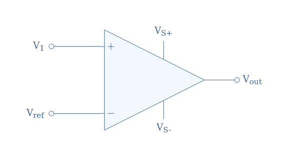
During this presentation section, we will pose and admit that Vref constitutes the ground, and therefore Vref=0. Moreover, we will admit that the supply is symmetrical (VS+=-VS-).
The functioning of this circuit is extremely simple and can be summarized depending on the value of V1:
- If V1>Vref, Vout=VS+
- If V1<Vref, Vout=VS-
The absence of feedback to the inverting input makes the amplifier to saturate up to the supply power level when the differential input Vin=V1-Vref=V1 becomes slightly higher than zero in absolute value
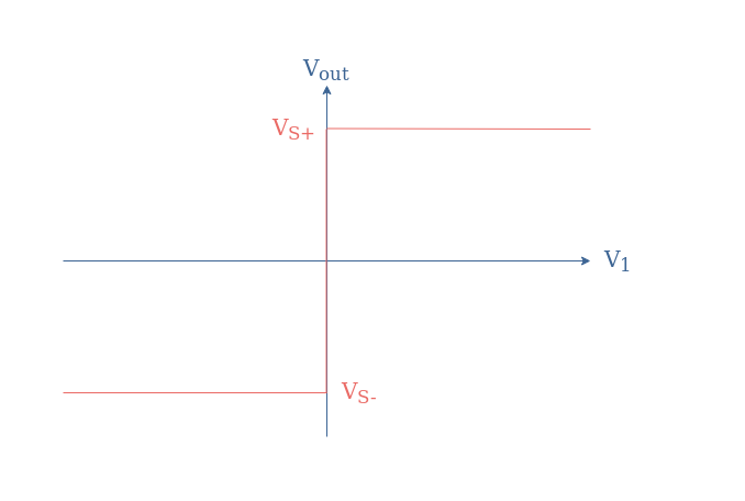
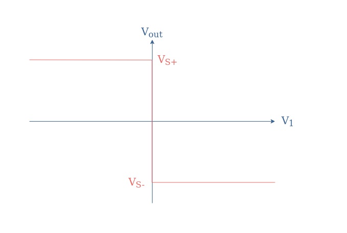
The input/output characteristic associated with the circuit of Figure 1 is a Heaviside-like function shown in Figure 2 below:
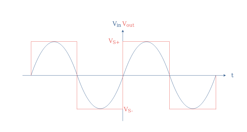
If a sine waveform is applied as an input, the comparator can be used to convert a sine to a square signal:
Inverting comparator
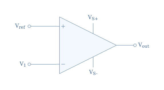
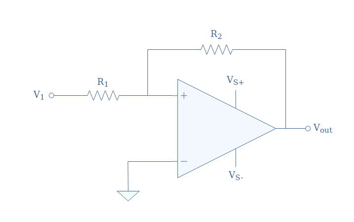
In the previous subsection, the signal to compare was applied to the non-inverting input while the reference was on the inverting input of the op-amp. However, the roles can be inverted in order to get an inverting comparator such as presented in Figure 4:
In this case, the value of the output is dictated by these two conditions:
- If V1<Vref, Vout=VS+
- If V1>Vref, Vout=VS-
The transfer characteristic for this configuration is also a Heaviside-like function but with the positive saturation happening for V1<0 and the negative for V1>0:
Translation of the tipping point
Some complexity can be added with a voltage divider in the reference branch to either the non-inverting or inverting comparator in order to translate the tipping point. The tipping point is the value of V1 for which the output suddenly changes from a high (resp. low) to a low (resp. high) value. In the previous section, the tipping point was always happening for V1=0.
Let’s consider the comparator presented in Figure 6:
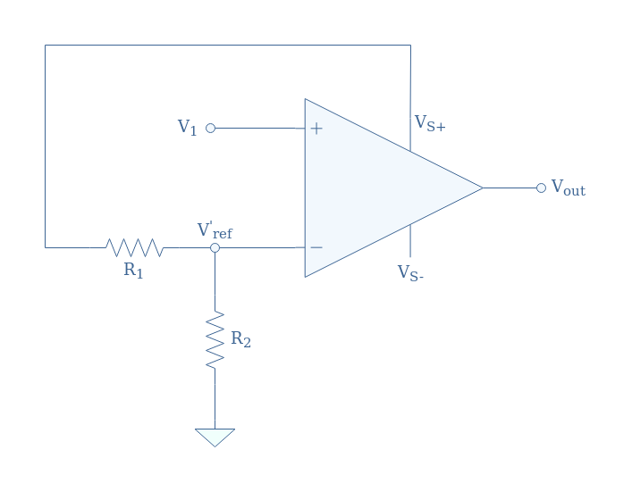
Thanks to the voltage divider, an alternative reference voltage labeled V’ref is supplied to the inverting input of the op-amp. This new reference satisfies the voltage divider formula: V’ref+=+VS(R2/(R1+R2)). Note that the voltage divider can also be supplied with the negative power supply VS-, in that case, the alternative reference presents a negative sign (we label it V’ref-).
These observations can be summarized in the following transfer characteristics:

If we consider an inverting comparator, the effect of the same voltage divider circuit will have the opposite effect. Indeed, if the voltage divider is supplied with the positive (resp. negative) power supply, the translation of the tipping point will be negative (resp. positive). Moreover, the signal is inverted such as presented in Figure 5.
Time-dependent input
The translation of the tipping point allows setting the threshold level of the comparator to a non zero level. When a variable input is applied to the circuit, such as the output of light or temperature sensor, a simple level detector can be made with this basic comparator.
Schmitt trigger
Non-inverting trigger
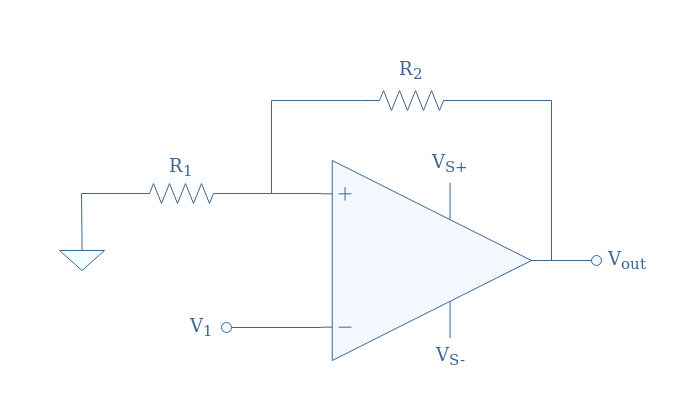
The translation of the tipping point can also be realized by adding a voltage divider circuit as a feedback loop in the non-inverting branch, the inverting branch is grounded (Vref=0). The full configuration is shown in Figure 9 below, it is also known as a Schmitt trigger, we take as an example the non-inverting comparator:
In the situation proposed in Figure 9, the differential input can be written Vin=V+-Vref=V+. Moreover, the voltage V+ can be written as a superposition of V1 and Vout thanks to Millman’s theorem:
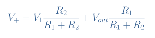
The differential input is equal to zero when V1=-Vout(R1/R2). Since the output value can only be equal to VS or -VS, there are two values of V1 that can be seen as tipping points, we label them VT+ and VT- for “threshold”:
- VT+=VS(R1/R2) is the upper threshold for which Vout=VS-→VS+
- VT-=-VS(R1/R2) is the lower threshold for which Vout=VS+→VS-
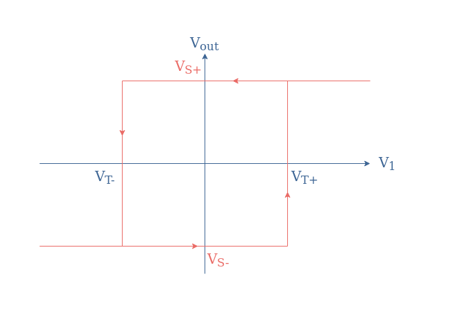
The input/output characteristic of a non-inverting Schmitt trigger is a hysteresis graph presented in Figure 10:
Inverting trigger
We can as well consider the same positive feedback for an inverting configuration:
In this case, the differential input can be written Vin=Vout(R1/(R1+R2))-V1, the input voltage V1 that cancels the differential input is therefore given by V1=-Vout(R1/(R1+R2)).
Depending on the sign of Vout, two thresholds specific to the inverting configuration can be defined:
- VT+=-VS(R1/(R1+R2))
- VT-=+VS(R1/(R1+R2))
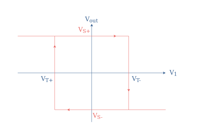
The associated hysteresis plot for the inverting Schmitt trigger is given in Figure 12:
Applications
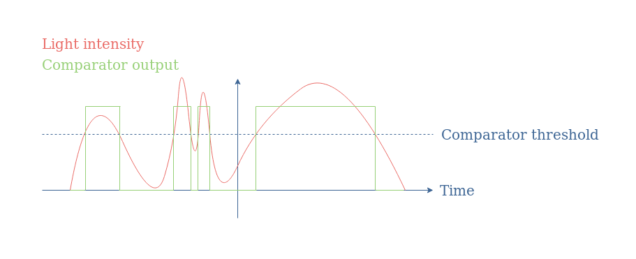
Schmitt triggers and comparators in general, as we briefly presented in Figure 8 are mainly used for the conversion of analogic signals to digital signals.
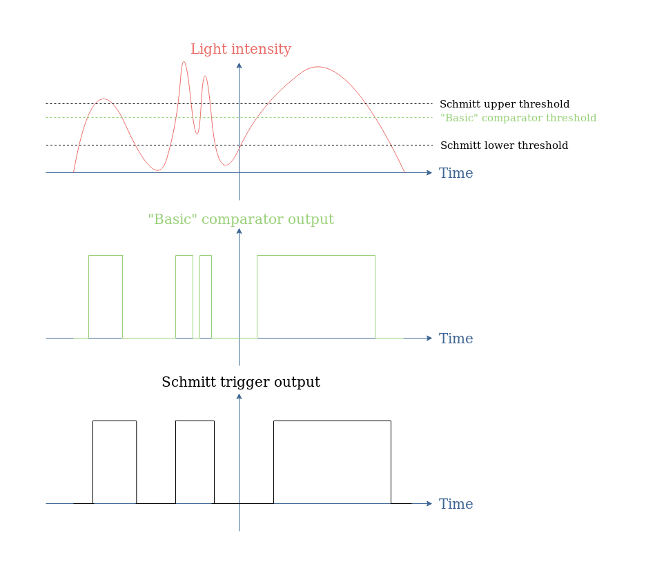
However, “basic” comparators present the disadvantage of being triggered by background noise. One of the very appreciated properties of Schmitt triggers is their noise immunity, which means that the comparator will switch between the low and high output states only when the input is effectively triggering it. Moreover, since the high output state is triggered by the upper threshold and the low output state by the low threshold, Schmit triggers usually add a delay in comparison with “basic comparators”.
When considering again Figure 8, we could imagine that during the second global light variation, the two peaks can be related to some noise (coming from the user for example).
Thanks to the hysteresis that can be achieved with a Schmitt trigger, if the lower threshold is set below the minimum noise level, the background noise does not trigger the comparator:
Conclusion
Comparators are operational amplifiers that are intentionally designed to work in open-loop or with positive feedback, which is both unstable and non-linear modes. Their output can only be equal to two different values, which correspond approximately to the power supply voltages. The output, or saturating voltages, depending on the input supplied. This input is being compared to a reference voltage which sets the threshold of the comparator.
In the second section, we have seen that the threshold voltage can be modified by adding a simple voltage divider circuit to the inverting branch of the op-amp. Basic comparators work in open-loop and present only one threshold, which makes them simple to design and with a fast response.
The third section focuses on Schmitt triggers which present the advantage to not be triggered by background noise, such as basic comparator do. Schmitt triggers do not work in open-loop configuration but instead with positive feedback to their non-inverting input. It allows them to have two threshold levels (high and low), as a consequence, their transfer characteristic is a hysteresis.


