The Summing OPAMP Amplifier
Introduction In most of our previous tutorials concerning operational amplifiers, only one input was applied to either the inverting or non-inverting op-amp's input. This new article will deal with a configuration known as the summing amplifier which gives an output that is proportional to a weighted sum of the multiple inputs present.
Introduction
In most of our previous tutorials concerning operational amplifiers, only one input was applied to either the inverting or non-inverting op-amp’s input. This new article will deal with a configuration known as the summing amplifier which gives an output that is proportional to a weighted sum of the multiple inputs present.
The inputs can either be applied to the inverting or non-inverting branches which give two possible configurations that will be separately presented in the first and second sections. They are commonly referred as the inverting summing amplifier and non-inverting summing amplifier and we will see what are their differences and similarities.
In a third section, the dual configuration of the summing amplifier, the subtracting amplifier, is investigated.
Inverting summing amplifier
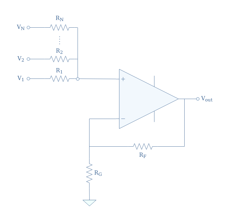
In Figure 1 we see the general circuit for an inverting summing amplifier:
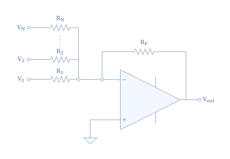
In this configuration, N inputs V1,V2,…,VN are applied to the inverting input of the op-amp through different resistor R1,R2,…,RN. The output Vout is feedbacked to the inverting branch through a resistor RF, the non-inverting input is grounded.
We can apply Millman’s theorem to V– in order to demonstrate the output relation of this circuit:
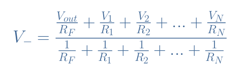
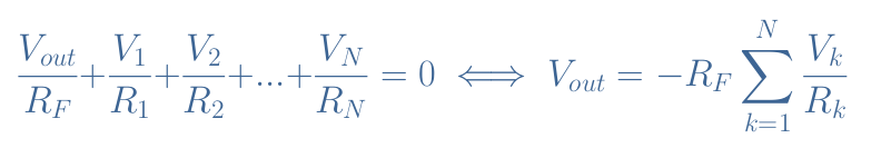
With the hypothesis of the ideal op-amp, i+=i–=0, and V+=V–=0, which leads to the output relation of the inverting summing amplifier:
It is interesting to note that if we equalize all the input resistors with the feedback resistor, R1=R2=…=RN=RF, we obtain a simplified version for Equation 1:
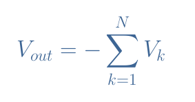
In this case, the sum is not weighted anymore, and the inverting summing amplifier adds the inputs negatively as the output signal phase is in opposition with the inputs.
Non-inverting summing amplifier
The non-inverting summing amplifier is a similar configuration to the inverting summing amplifier. However, the inputs here are applied to the non-inverting input while the inverting branch is connected to both the op-amp’s output through a feedback resistor RF and grounded through a resistor RG.
We can apply Millman’s theorem to V+ in order to demonstrate the output relation of this circuit:
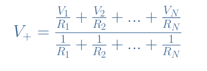
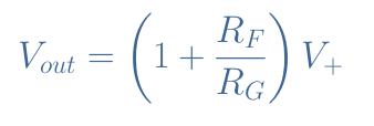
Since the voltage gain Vout/Vin=Vout/V+ of a non-inverting configuration is given by 1+(RF/RG), we can conclude that the general relation for the non-inverting summing amplifier output is given by Equation 3:
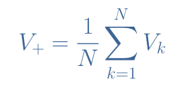
The expression of V+ can be extremely simplified if we pose R=R1=R2=…=RN, we get indeed:
Moreover, we can also pose (1+RF/RG)=N in order to get a direct sum of the input voltages:
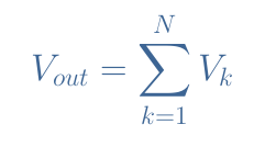
With these two conditions, we can see that the output voltage is a direct sum of the input signals as the sum is not weighted and no phase difference is present.
To conclude this section we can draw a little comparison between the inverting and non-inverting summing configurations. The advantage of the inverting configuration is that even in the general case, the output is simply expressed as a function of the different resistor and input values.
In a non-inverting configuration, the output is always in phase with the inputs which save the trouble to use an inverting buffer to rectify the signal. Moreover, the non-inverting configuration presents the property of having a much higher input impedance which is an advantage to properly inject the desired voltages from a source (microphone for example) to the inputs of the op-amp.
However, we have seen that the output voltage is a simple weighted sum only under a condition of equality between all the resistors in the circuit.
Subtracting amplifier
If the inputs are both applied to the inverting and non-inverting pins of an op-amp, a subtracting configuration is realized such as presented in Figure 3:
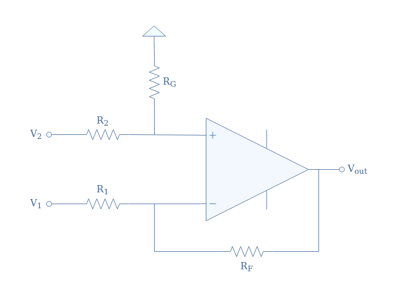
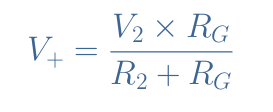
The voltage V+ can be expressed by a voltage divider formula:
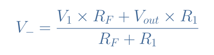
The voltage V– is expressed thanks to Millman’s theorem:
After reminding that V+=V–, a few steps of simplification lead to the general output expression of the subtracting amplifier:
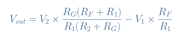
We can simply show by equalizing the two factors that if the condition RFR2=RGR1 is met, the output formula can be simplified to Equation 6:
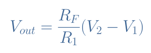
This condition can be achieved by equalizing all the resistances: R1=R2=RG=RF. In that case, since RF=R1, Equation 6 can be reduced to a direct subtraction Vout=V2-V1.
Applications
Audio mixer
Consider an inverting summing amplifier with three inputs such as presented in Figure 4:
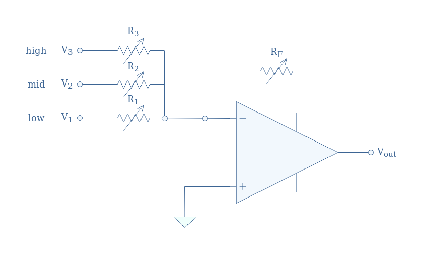
The resistors here are replaced by potentiometers in order for a user to directly control the output signal.
This type of configuration can be used in the audio domain where different pitches can be separately processed through an amplifier before being added together with possibly different prefactors.
Typically, the frequency ranges are given by:
- low: 20 Hz to 500 Hz
- mid: 500 Hz to 6 kHz
- high: 6 kHz to 20 kHz
According to Equation 1, the output signal of this configuration is given by:
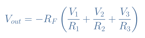
We can clearly identify that the potentiometer RF controls the global gain of the output, increasing or decreasing its value will simultaneously affect all the frequencies. On another hand, the potentiometers R1, R2, R3 only affect respectively the low, mid, and high pitches and they will enable the user to balance or unbalance certain frequencies.
We can note that if we want the output to be in phase with the different inputs, a simple inverting buffer can be used to rectify it.
Digital to Analogue Converter (DAC)
A DAC is a summing amplifier based circuit that converts binary data (0 and 1) into an analog signal (a real number). An example of this circuit with four binary inputs known as a four-bit DAC and is presented in Figure 5:
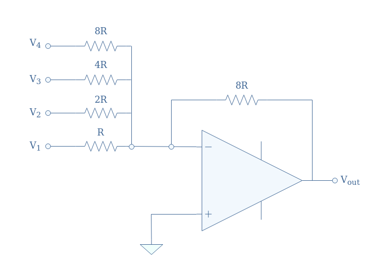
The values of the resistor are not chosen randomly, their values always need to double from the previous branch. This ensures a proper conversion from a binary number to a decimal number.
As an example, consider the binary four-bit input 1101 (V1=1 ; V2=1 ; V3=0 ; V4=1). According to Equation 1, the output is given by:
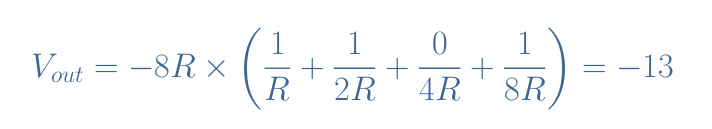
This validity of this result can be confirmed when we manually convert the same input to a decimal number: (1101)decimal=(1×23)+(1×22)+(0×21)+(1×20)=13.
In practice, the circuit shown in Figure 5 can only be implemented up to a certain number of bits depending on the precision of the resistors that must exactly double their value for each added bit. An alternative circuit known as the R-2R Ladder DAC is preferred for higher binary numbers.
Conclusion
A summing amplifier can either be based on an inverting or non-inverting configuration. Despite the high input impedance and in-phase output signal that the non-inverting summing amplifier can provide, the inverting summing amplifier is more common as it’s output is a simple weighted sum.
Indeed, the non-inverting summing output is a simple weighted or direct sum of the inputs only when a condition of equality between all the resistors in the circuit is met.
After presenting and detailing these two summing configurations, a third section has presented the subtracting amplifier which slightly differs from the summing amplifiers and is used to subtract two or more signals by applying them both on the inverting and non-inverting pins.
Finally, in the last section, we present the possible applications of the summing amplifiers. Indeed, an inverting summing amplifier can be used as an audio mixer in order to separately control each input importance, the inputs can, for example, be frequency ranges or different instruments outputs.
We also show that summing amplifiers can be used as a simple digital to analog converters when the resistance value for each added bit is doubled.


