Exclusive OR Gate
Exclusive-OR Gate The Exclusive-OR gate gives an output given by the expression “A or B not Both”. It means that the output of the Exclusive-OR gate is low when both inputs “A” and “B” are at the same logic level i.e.
Exclusive-OR Gate
The Exclusive-OR gate gives an output given by the expression “A or B not Both”. It means that the output of the Exclusive-OR gate is low when both inputs “A” and “B” are at the same logic level i.e. both “HIGH” or “LOW”. In the case of, either “A” or “B” that is “01” or “10” the output of the Exclusive-OR gate will be “HIGH”.
The Exclusive-OR is also referred to by writing only Ex-OR or XOR. The Ex-OR is a very useful logic and is mostly used in arithmetic, error detection, and computational circuits.
The logic Ex-OR is constructed using basic logic gates which are AND, OR, and NOT gates. Although using these basic logics many functions/ logics can be constructed but the importance of Ex-OR logic has led it to be constructed as a separate logic gate. Because of its construction from multiple basic logic gates, it is also called a “hybrid” logic gate. The logic OR gate, which was discussed in the previous article, is an inclusive-OR function which states to include both “A” and “B” states in logic “HIGH” output. Whereas, as mentioned earlier in this article, the Ex-OR logic excludes states of both “A” and “B” inputs from the logic “HIGH” output. Because of the inclusion and exclusion of both input states, the logic OR is termed as inclusive-OR and Exclusive-OR, respectively. In simple words, the output of Ex-OR logic goes “HIGH” only when both inputs are different.
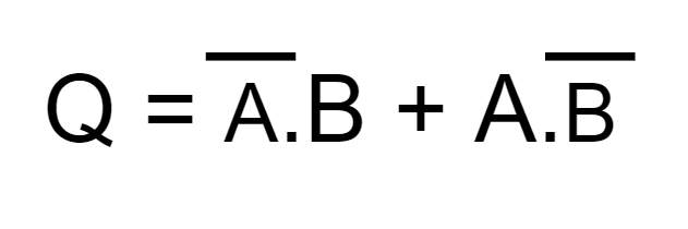
The Boolean algebraic equation is given below:
Logic Ex-OR Gate Symbol & Truth Tables
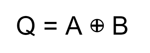
The representation of an Ex-OR logic by a symbol is shown in the following figure. Basically, a two-input Ex-OR logic is a modulo two-adder as it gives the sum of two binary numbers.

The truth table of a two-input Ex-OR logic is shown below:
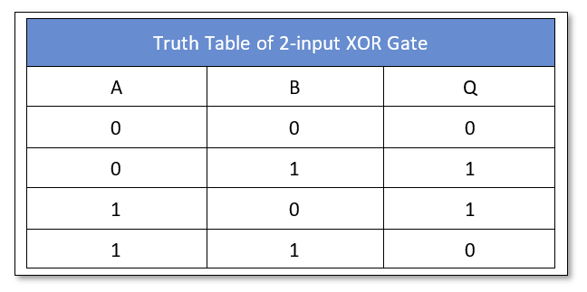
It is clear from the truth table that when inputs are at different levels i.e. either “01” or “10” then the Ex-OR logic output is “HIGH” and in case the inputs are at the same level then output is “LOW”. In other words, “A” or “B”, not both!.
The Boolean equation of Ex-OR logic is:
The expression for an inclusive-OR logic consists of a plus symbol between the operands and denotes a logical addition/summation of the inputs. Whereas, the expression of Exclusive-OR logic comprises a plus sign within a circle between the operands. The circle basically describes a direct sum of sub-objects.
The logic function performed by a more than two-input Ex-OR gate is basically a modulo 2 sum and is not an Ex-OR logic. The truth table of a three-input Ex-OR logic is as follow and can be expanded to include any number of inputs:
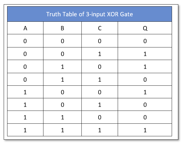
For three input Ex-OR logic, when there is an odd number of inputs with logic “HIGH” then the output is “HIGH” and this characteristic makes the Ex-OR an odd gate. Moreover, the ability of Ex-OR to compare logics at the input and to produce results at the output based upon inputs is really useful in arithmetic, error-detection, and computational circuits.
The symbol and expression of a 3-input Ex-OR logic are given below:

Ex-OR (XOR) Logic Circuit
Using the above equation of a two-input Ex-OR logic, an equivalent circuit can be constructed which is shown in the following figure.
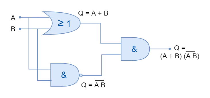
The above equivalent Ex-OR logic comprises AND, OR, and NAND logics. However, it is not a good practice to include multiple logics for the construction of logic gates and a better Ex-OR circuit can be constructed using only NAND logic gates.
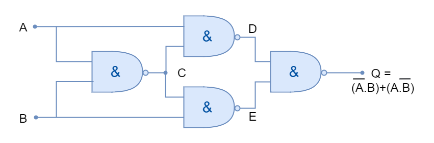
The construction of Ex-OR gate using NAND gates only is shown below:
The Exclusive-OR logic gates are helpful in performing arithmetic operations such as addition in the form of Adders and Half-Adders. They have the ability to provide a “carry-bit” or as a controlled inverter to facilitate the addition of larger binary numbers.
Commercially Available E-OR (XOR) Gates
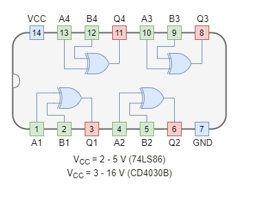
The XOR logic gates are available in both TTL and CMOS logic families. The most commonly used XOR logic packages are:
CMOS based XOR Gate IC Package
- CD4030B Quad 2-input
TTL based XOR Gate IC Package
- 74LS86 Quad 2-input
Example of XOR Logic
In the following figure, an XOR gate is used to drive a 12V relay to switch on the lamp using NI Multisim. The XOR gate (74LS86) turns off the relay when all of the inputs are connected to VCC/ Ground. The relay thus turns off the lamp through an external circuit of 12V. When one of the inputs is connected to VCC, XOR logic goes “ON” turning the relay and lamp to “ON” state.
Conclusion
- The output of the Ex-OR logic is “LOW” when all of the inputs are in logic “HIGH” or “LOW” states.
- The Ex-OR gate outputs logic “HIGH” only when inputs are different (not the same).
- The Ex-OR logic is not a basic logic but obtained the status of logic due to its usefulness and versatility.
- It is mostly used in arithmetic, computational and error-detecting circuits.
- It is also mostly used as a logic comparator because of its ability to compare logical inputs.
- It is widely used in Full-Adders and Half-Adders circuits to binary numbers,
- The Ex-OR logic gates are commercially available in both TTL and CMOS packages.
- An external circuit can be controlled by Ex-OR logic with the use of a magnetic relay.


