Logic OR Function
Logic OR Function The output of Logic OR Function is true when one or more of its inputs are in true logic states otherwise the output of Logic OR Function will be false. Likewise, the output of Logic OR Function will be false ONLY when all of its inputs are in false logic states.
Logic OR Function
The output of Logic OR Function is true when one or more of its inputs are in true logic states otherwise the output of Logic OR Function will be false.
Likewise, the output of Logic OR Function will be false ONLY when all of its inputs are in false logic states. The TRUE logic output follows that either one “OR” more inputs are TRUE for Logic OR Function. Similar to the AND logic, the OR logic follows the Boolean algebra and relevant theorems.
The Logic OR Function, in its original form, includes all of its input states for making logical decisions and as such termed “Inclusive OR”. The other variant which outputs “LOW” (excludes) when inputs have similar states is “Exclusive OR”. For example, when all inputs are at state “LOW” or “HIGH” (similar states of inputs) then the output of “Exclusive OR” will be “LOW”. In contrast, the “Inclusive OR” takes into account all input states for logical decision making i.e. when all inputs are at logic “HIGH” states then its output is “HIGH”.
In the following figure, a symbol along with the algebraic function of logic OR gate is shown.

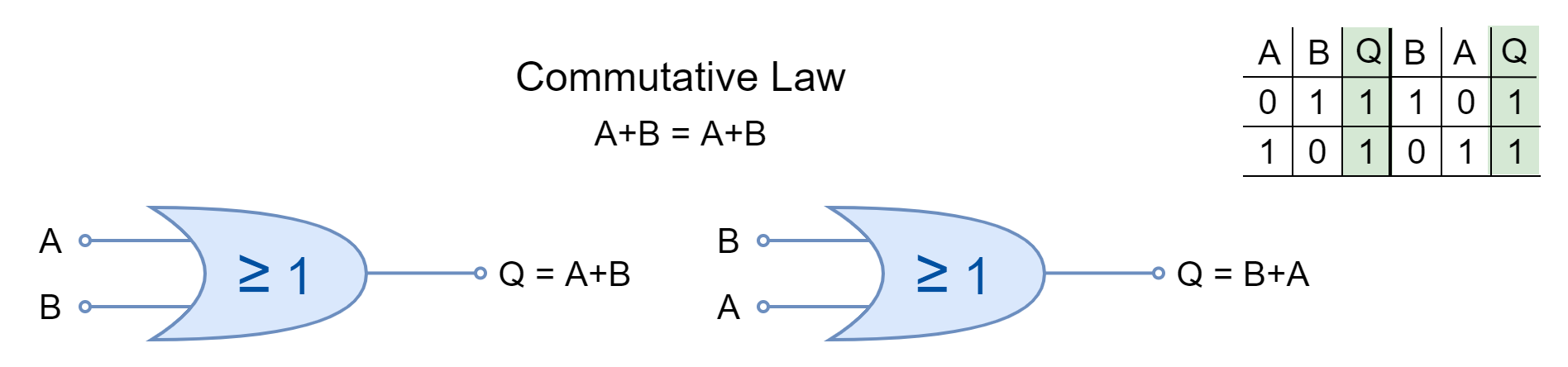
In terms of Electrical Circuit, the logic OR functions are represented by switches connected in “Parallel”. In Boolean Algebra, the logic OR function is the sum of inputs (variables) and is denoted by a plus (+) between the inputs i.e. A+B represents an OR logic on inputs A & B. The occurrence of a state of operation of a switch is independent of the order in which they take place. It means that the logic OR function follows the Commutative Law i.e. A + B = B + A. According to Commutative Law, the output is independent of the position of a variable or input.
Presentation of OR Function using Switches
In the following figure, an electrical circuit comprising of two switches (A & B), a battery, and a lamp is shown. The electrical circuit shown is equivalent to logic OR function where switches A & B represents logic OR function’s inputs.
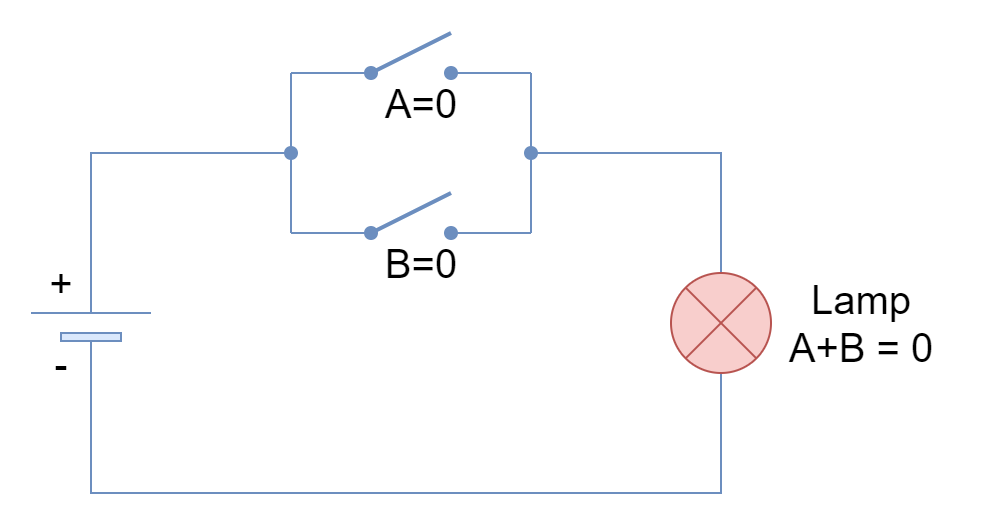
The logical states of “0” & “1” represent a switch with “Open” & “Close” positions, respectively.
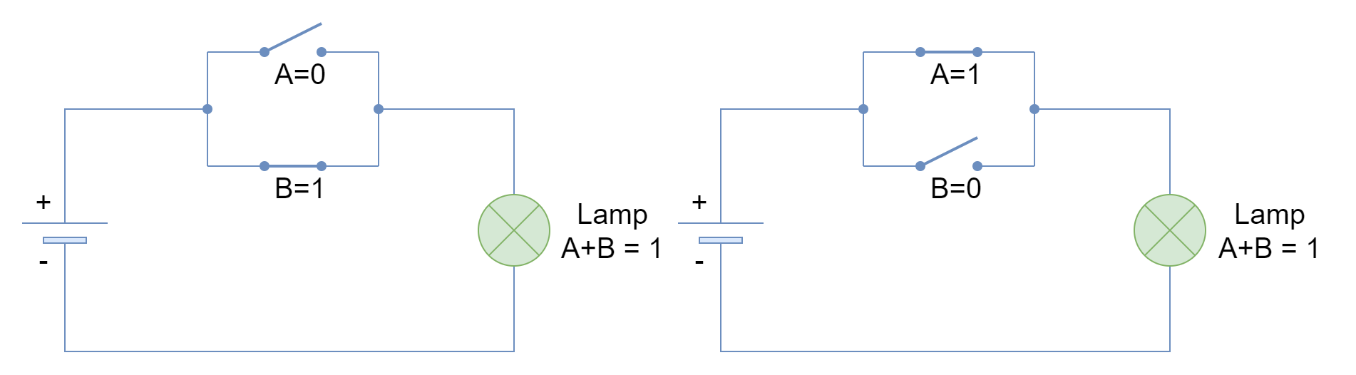
When both inputs are FALSE or “0” then both switches are open and the lamp remains at FALSE/ OFF state. However, when any of both inputs, irrespective of order or placement, is TRUE then the lamp turns to TRUE/ ON state as shown in the following figure.
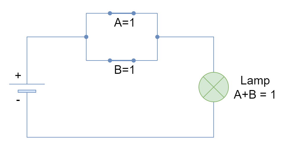
Likewise, when both of the inputs are TRUE or “1” then the lamp turns to TRUE or ON state as well. The parallel combination of switches truly depicts the logic OR function where any one of the switches (inputs) is required to be TRUE to give a TRUE output.
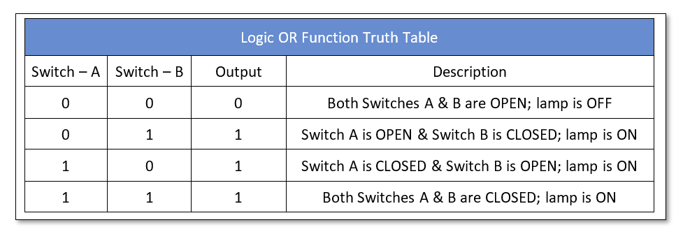
Logic OR Truth Table
The above case of parallel switches is represented in the following truth table.
Boolean Algebra Laws
A brief overview of Boolean Algebra Laws relevant to logic OR is given.
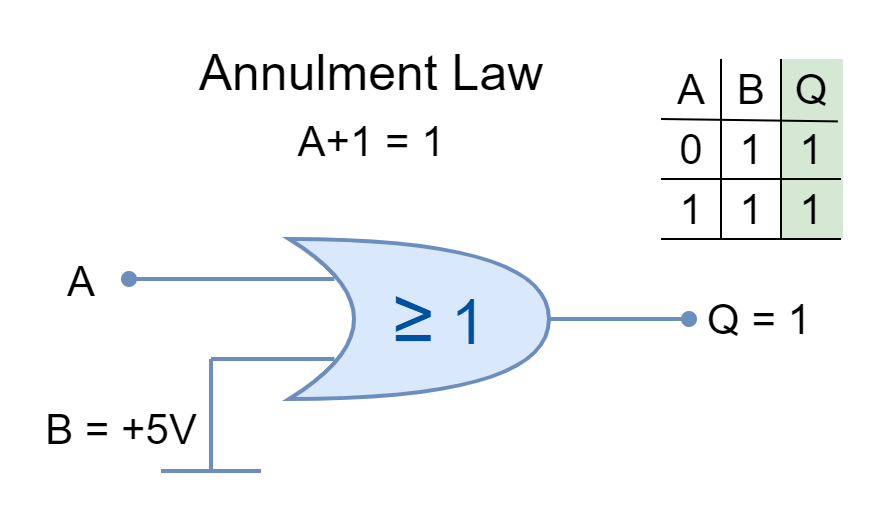
Annulment Law
The input AND’ed by ‘0’ or OR’ed by ‘1’ is stated as Annulment Law. It nullifies or diminishes the effect of the other input.
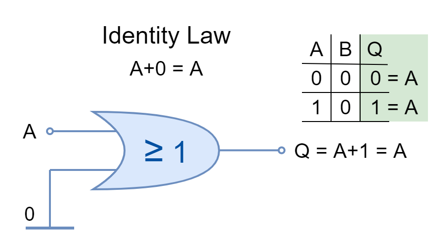
Identity Law
The input AND’ed by ‘1’ or OR’ed by ‘0’ is stated by Identity Law. It keeps the identity of the input.
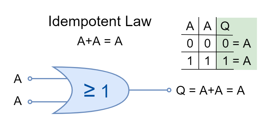
Idempotent Law
The same inputs AND’ed or OR’ed together are stated under Idempotent Law. The logical operation can be applied multiple times without changing the result.
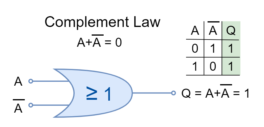
Complement Law
In Boolean Algebra, the complement is the opposite of a logical input such as ‘0’ is the complement of ‘1’ and vice versa. The input and its complement AND’ed or OR’ed together is described by Complement Law.
Commutative Law
The commutative law states that changing the order of operands (variables or inputs) does not change the result. In Boolean Algebra, the inputs can be interchanged without changing the results under commutative law.
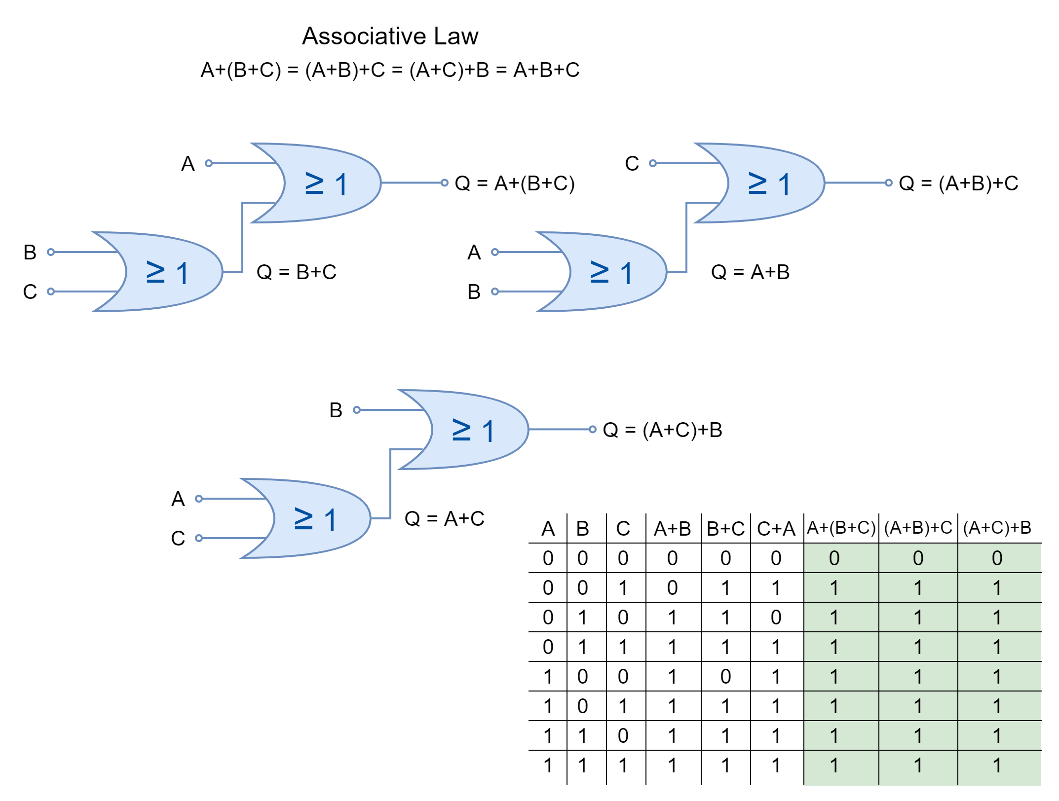
Associative Law
The associative law of multiplication states that the operands grouped differently in multiplication produce the same result. The inputs OR’ed together can be placed interchangeably to form different groups under the Associative Law.
Commercially Available Logic OR Gates
The logic OR gates are available in form of I.C. packages which contain multiple OR gates with multiple inputs to each gate. The selection depends merely on the application and the number of logic are required. They come in both Transistor-Transistor Logic (TTL) and Complementary Metal Oxide Semiconductor (CMOS) family packages. A few commercially available logic OR gates are given below:
- TTL 74LS32 2-input Quadruple OR Gates
- CMOS 4071 2-input Quadruple OR Gates
- CMOS 4075 3-input Triple OR Gates
- CMOS 4072 4-input Dual OR Gates
Conclusion
- The logic OR function gives output FALSE when all of its inputs are in a FALSE state.
- Any of the inputs in the TRUE state will lead the OR function to the TRUE output.
- The logic OR function can be represented by an electrical circuit having two switches in parallel. When any of the switches is closed (input at TRUE states) then supply passes to the load/ lamp.
- The logic OR gates can be cascaded together to obtain logic OR having more than two inputs.
- The commercially available packages come in different I.C. packages. Each IC package contains multiple OR gates with two or more inputs. The selection merely depends upon the application requirement.


