Temperature Sensors
This article introduces temperature sensors that detect heat using either direct physical contact or non-contact methods like radiation and convection. It also introduces a few popular types, including bending bi-metallic strips, thermistors, and RTDs.
Introduction
The most widely utilized sensors are those that can measure heat or temperature. These temperature sensor types range from straightforward ON/OFF thermostats that regulate a home’s hot water heating system to extremely sensitive semiconductor models that can regulate intricate process control furnace facilities.
We recall from science studies in school that the motion of molecules and atoms produces heat (kinetic energy), and the more movement, the more heat is produced. By measuring the quantity of heat energy or even cold produced by a system or item, temperature sensors enable us to “sense” or detect any change in temperature and provide an analog or digital output.
A variety of temperature sensors are available, and each one has unique properties based on its intended use. There are two fundamental physical types of temperature sensors:
- Contact Temperature Sensor Types- These sensors employ conduction to track temperature changes and must be in direct physical contact with the object they are sensing. They are useful for detecting gases, liquids, and solids at a variety of temperatures.
- Non-contact Temperature Sensor Types- These sensors track temperature variations by using radiation and convection. They can be used to detect radiant energy being transferred from an object in the form of infrared radiation (the sun) or to detect liquids and gases that emit radiant energy as heat rises and cold settles to the bottom in convection currents.
Electro-mechanical, resistive, and electronic are the three categories into which the two primary types of touch, or even non-contact temperature sensors, can be further subdivided. All three of these types are covered in the sections that follow.
The Thermostat as a Temperature Sensor
The thermostat is an electromechanical temperature sensor or switch of the contact type. It is essentially made of two distinct metals, such as copper, tungsten, nickel, or aluminium, that are joined to form a bi-metallic strip. When the strip is heated, the two dissimilar metals’ varying linear expansion rates cause a mechanical bending movement.
The bi-metallic strip is widely used to control hot water heating elements in boilers, furnaces, hot water storage tanks, and vehicle radiator cooling systems. It can be used as an electrical switch on its own or as a mechanical means of operating an electrical switch in thermostatic controls.
The Bi-Metallic Thermostat
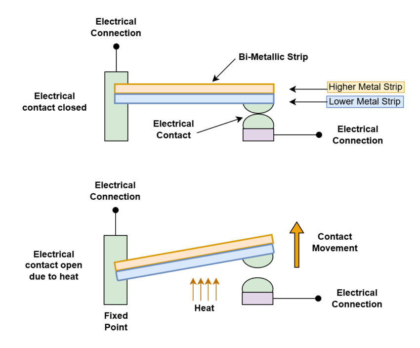
Fig-1: Bi-metallic Thermostat
The thermostat is made up of two metals that have different temperatures that are attached to one another. The thermostat’s connections close, and current flows through it when it’s chilly. As the temperature rises, the bonded bi-metallic strip bends up (or down) to open the contacts and stop the current from flowing because one metal expands more than the other.
Bi-metallic strips can be divided into two major categories depending mostly on how they behave under temperature variations. There are the slower “creep-action” varieties that progressively shift their position as the temperature varies, and the “snap-action” versions that instantly cause a “ON/OFF” or “OFF/ON” type action on the electrical contacts at a specific temperature point.
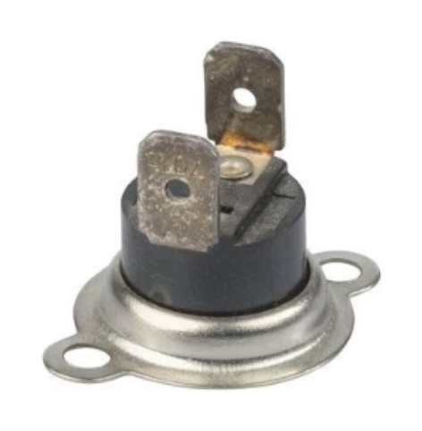
Fig-2: ON/OFF Thermostat
Snap-action thermostats are frequently seen on walls to regulate the domestic heating system and are used to regulate the temperature set point of immersion hot water tanks, ovens, and irons.
Typically, creepers are made up of a bi-metallic coil or spiral that gradually coils up or unwinds in response to temperature changes. Because creeper-type bi-metallic strips are thinner and longer than normal snap-on/OFF types, they are generally more sensitive to temperature changes, which makes them perfect for use in temperature gauges, dials, and other devices.
Standard snap-action thermostats have a huge hysteresis range from when the electrical contacts open to when they shut again, which is a major drawback for using them as temperature sensors, despite their low cost and wide operating range. For instance, even though it is set at 20 °C, it might not open until 22 °C or close until 18 °C.
Therefore, there may be a significant temperature variation. Commercially available bi-metallic thermostats for residential usage have temperature adjustment screws that enable pre-setting of the hysteresis level and a more accurate desired temperature set-point.
The Thermistor as a Temperature Sensor
Another kind of temperature sensor is called a Thermistor, which combines the terms THERM-ally sensitive res-ISTOR. A thermistor is a unique kind of resistor that, in response to temperature changes, alters its physical resistance.
Thermistors are often composed of ceramic materials, such as glass-coated nickel, manganese, or cobalt oxides, which are prone to corrosion. Their accuracy, repeatability, and quick reaction to temperature changes are their primary advantages over snap-action versions.
Fig-3: An NTC thermistor.
Another kind of temperature sensor is called a Thermistor, which combines the terms THERM-ally sensitive res-ISTOR. A thermistor is a unique kind of resistor that, in response to temperature changes, alters its physical resistance.
Thermistors are often composed of ceramic materials, such as glass-coated nickel, manganese, or cobalt oxides, which are prone to corrosion. Their accuracy, repeatability, and quick reaction to temperature changes are their primary advantages over snap-action versions.
Most thermistor types have a negative temperature coefficient of resistance, or NTC, meaning that as the temperature rises, their resistance value decreases. Of course, some have a positive temperature coefficient, or PTC, meaning that as the temperature rises, their resistance value increases.
Thermistors are made of semiconductor materials of the ceramic kind that use metal oxide technology, such as nickel, cobalt, and manganese. To provide a relatively quick response to temperature changes, the semiconductor material is typically shaped into small, pressed discs or balls that are hermetically sealed.
Thermistors are graded according to their power rating about the current passing through them, their resistive value at room temperature (often at 25 °C), and their time constant (the amount of time it takes for them to react to a temperature change). Like resistors, thermistors can have resistance values ranging from tens of MΩ to a few Ohms at room temperature; however, kilo-ohm values are typically utilized for sensing applications.
Since thermistors are passive resistive devices, a current must flow through them to provide a voltage output that can be measured. Then, to create a potential divider network, thermistors are often connected in series with an appropriate biasing resistor. The resistor selection provides a voltage output at a predetermined temperature point or value, for instance:
Temperature Sensor Example
Let’s take a look at the circuit shown in Figure 4.
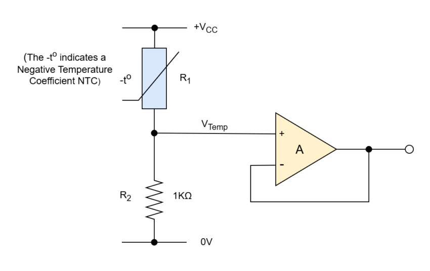
Fig-4: Temperature sensor circuit with voltage follower amplifier output.
At 25°C, the resistance value of the following thermistor is 1KΩ, and at 100°C, it is 100Ω. The thermistor is connected in series with a 1kΩ resistor with a 12 V power source. Calculate the voltage drop across the thermistor and, consequently, its output voltage (VOUT) for both temperatures.
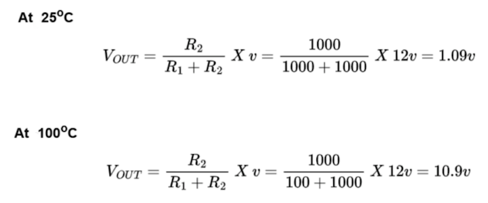
Equations 1 and 2: Temperature sensor circuit with voltage follower amplifier output
By adjusting the fixed resistor value of R2 (in our example, 1kΩ) to a potentiometer or preset, the output voltage can be obtained at a predetermined temperature set point, for example, 5v output at 60oC. By varying the potentiometer, a specific output voltage level can be obtained over a wider temperature range.
However, it should be mentioned that thermistors are non-linear devices, and that the semiconductor materials used to make them mostly determine their standard resistance values at normal temperature. Since the thermometer’s resistance changes exponentially with temperature, its beta temperature constant (β) can be used to determine its resistance at any given temperature.
On the other hand, the current received in response to a voltage given to the divider/bridge network is linear with temperature when employed with a series resistor, as in a Wheatstone Bridge type arrangement or a voltage divider network. The output voltage across the resistor then increases in proportion to the temperature.
Resistive Temperature Detectors (RTD)
The Resistance Temperature Detector, or RTD, is another kind of electrical resistance temperature sensor. High-purity conducting metals like platinum, copper, or nickel coiled into a coil and whose electrical resistance varies with temperature, much like a thermistor, are used to make RTDs, which are precise temperature sensors. Also accessible are thin-film RTD’s. A thin layer of platinum paste is applied to a white ceramic substrate in these devices.
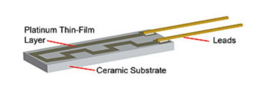
Fig-5: Resistive temperature detector.
Although resistive temperature detectors contain positive temperature coefficients (PTC), they produce incredibly accurate temperature readings because of their highly linear output, in contrast to thermistor. But because of their extremely low thermal sensitivity, a change in temperature only results in a very slight output change—for instance, 1Ω/oC.
Platinum Resistance Thermometers, or PRTs, are the most popular forms of RTDs. The most widely accessible of these is the Pt100 sensor, which has a typical resistance value of 100Ω at 0oC. Unfortunately, Platinum is expensive, which is one of the primary drawbacks of this type of gadget.
RTDs are passive resistive devices, like thermistors, and may provide an output voltage that rises linearly with temperature by running a steady current through the temperature sensor. With a working temperature range of -200 to +600oC, a typical RTD has a base resistance of roughly 100Ω at 0oC and rises to about 140Ω at 100oC.
Since the RTD is a resistive device, we must pass a current through it while keeping an eye on the voltage that results. However, any change in resistance brought on by the resistive wires’ internal heat as current passes through them, or I2R (Ohm’s Law), results in a reading inaccuracy. A Wheatstone Bridge network, which includes extra connecting wires for lead-compensation and/or connection to a constant current source, is typically used to connect the RTD to overcome this.
The Thermocouple as a Temperature Sensor
When it comes to temperature sensors, the thermocouple is the most widely used type. Because of their small size, thermocouples respond quickly to temperature changes and are simple and easy to use. These factors have made them popular. Thermocouples can detect temperatures below -200°C and well over 2000°C, which is the widest range of any temperature sensor.
In a nutshell, thermocouples are thermoelectric sensors made up of two junctions of dissimilar metals, like copper and constantan, that have been crimped or welded together. The reference (cold) junction and the measuring (hot) junction are maintained at a consistent temperature. As seen here, a voltage is created across the junction when the two junctions have different temperatures. This voltage is then utilized to measure the temperature sensor.
Thermocouple Construction
A thermocouple works on a very basic and simple principle. When two dissimilar metals, like copper and constantan, fuse together, a “thermo-electric” effect is created at their junction, resulting in a constant potential difference between them of just a few millivolts (mV). Because a temperature gradient is created along the conducting wires, creating an electromagnetic field (emf), the voltage difference between the two junctions is known as the “Seebeck effect.” A thermocouple’s output voltage is then determined by variations in temperature.
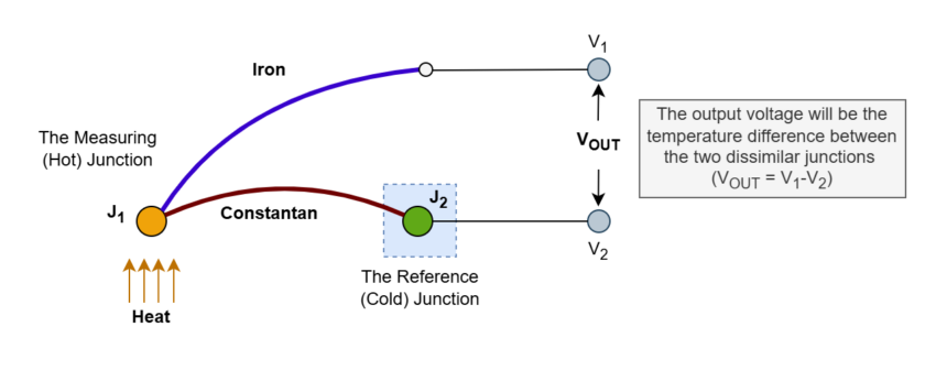
Fig-6: Thermocouple construction
When both junctions are at the same temperature, there is no potential difference between them; in other words, there is no voltage output because V1 = V2. On the other hand, a voltage output proportional to the temperature differential between the two junctions, V1 and V2, will be detected when the junctions are connected within a circuit and are both at different temperatures. Depending on the properties of the two dissimilar metals used, this voltage differential will increase with temperature until the junction’s peak voltage level is reached.
A wide range of materials can be used to create thermocouples, which allow for the measurement of extremely high or low temperatures, from -200°C to over 2000°C. The user can select the appropriate thermocouple sensor for a given application thanks to internationally recognized standards that include thermocouple color codes and a wide range of materials and temperatures. Below is the British color code for standard thermocouples.
Thermocouple Color Codes
Table-1: Thermocouple Color Codes
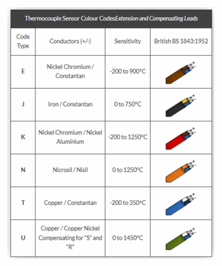
For general temperature monitoring, the three most widely used thermocouple materials are nickel-chromium (Type K), copper-chromium (Type T), and iron-chromium (Type J). A thermocouple’s output voltage is just a few millivolts (mV) for a temperature change of 10 degrees Celsius, and as a result, some kind of amplification is typically needed.
Thermocouple Amplification
Either a discrete amplifier or an operational amplifier must be carefully chosen since the thermocouple must have good drift stability to avoid recalibration at regular intervals. For most temperature sensing applications, the chopper and instrumentation type of amplifier is therefore used.
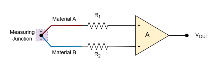
Fig-7: Thermocouple Amplification
Other types of temperature sensors that aren’t covered here include indicators, color-changing inks or dyes, semiconductor junction sensors, infrared and thermal radiation sensors, and medical thermometers.
Conclusion
- Temperature sensors are broadly categorized into contact and non-contact types. Contact sensors (e.g., thermostats, thermistors, RTDs, thermocouples) require physical contact, while non-contact sensors detect temperature via radiation or convection (e.g., infrared sensors).
- Thermostats are electro-mechanical contact sensors using bi-metallic strips that bend with heat, creating or breaking electrical connections. They come in snap-action (quick ON/OFF) and creep-action (gradual response) types, and are commonly used in home heating systems.
- Thermistors are temperature-sensitive resistors made from ceramic materials. Most are NTC (Negative Temperature Coefficient), meaning resistance decreases with increasing temperature. They’re precise, fast-responding, but nonlinear.
- RTDs (Resistive Temperature Detectors) use metals like platinum and have a positive temperature coefficient, making them highly accurate and stable. Their resistance increases linearly with temperature but changes slowly, requiring compensation circuits for accuracy.
- The most widely used type, thermocouples, consists of two dissimilar metals forming junctions. They generate a voltage (via the Seebeck effect) based on the temperature difference between the junctions, and they work across a very wide temperature range (-200°C to over 2000°C).


