Mastering the Curve: Layout Strategies for FPC Bend Radius and Reliability
Learn how early layout evaluation and system planning can help ensure long-term reliability for flexible printed circuits.
Flexible printed circuits are often selected because they solve mechanical packaging problems that rigid boards cannot. They can fold around batteries, move through hinges, connect stacked modules, and reduce connector count in compact products. But the same mechanical freedom also creates one of the most common reliability risks in flex and rigid-flex assemblies: the bend area is reviewed too late.
If bend radius is checked only after the layout is finished, engineers may discover that copper traces run through a high-strain zone, vias sit too close to a transition, stiffeners end in the wrong place, or the finished stackup is too thick for the expected movement. At that point, the fix can require a mechanical redesign, a new stackup, or a delayed prototype.
The better approach is to screen bend radius before layout release and treat the bend zone as a mechanical design feature, not just an electrical routing area.
Start With the Bend Mode
The first question is whether the flex area is static or dynamic, as they require different radius assumptions and validation plans (Figure 1).
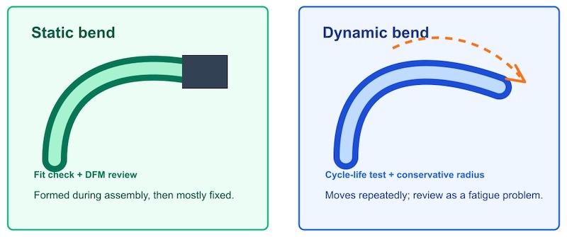
Figure 1. When beginning a new design, the FPC application must first be categorized as either static or dynamic.
A static bend is formed during assembly and then remains mostly fixed during product life. Examples include a folded interconnect inside a camera module or a flex tail wrapped once into a compact enclosure. Static bends can usually tolerate a tighter radius than moving applications, but they still need controlled geometry and good transition design.
A dynamic bend moves repeatedly during use. Examples include hinges, sliding mechanisms, wearable devices, robotic sensors, and other assemblies where the circuit bends thousands or millions of times. Dynamic flex zones need a larger radius, simpler copper geometry, and more conservative strain limits.
Many early design mistakes come from applying static bend assumptions to a dynamic application. If the bend will move in service, the layout should be reviewed as a fatigue problem, not just a packaging problem.
Estimate Radius From Finished Thickness
Bend radius is commonly discussed as a multiple of finished flex thickness (Figure 2). This is useful because strain increases as the bend radius becomes smaller relative to the stack thickness.
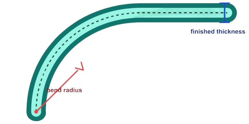
Figure 2. The ratio of the finished FCP thickness to the bend radius is an important design factor.
As a practical screening rule, simple static bends may start around a few times the finished thickness, while dynamic applications often need much larger ratios. Exact requirements depend on material, copper thickness, adhesive system, layer count, coverlay, and cycle life. The important point is that the calculation should use the finished flex thickness, not only the polyimide core thickness.
Engineers should also confirm whether the bend area is single-sided, double-sided, or multilayer. A single copper layer near the neutral axis is generally easier to bend than a thick multilayer structure. If the design requires multiple copper layers through a bend zone, the radius should be reviewed more conservatively and confirmed with the fabricator.
Keep Copper Geometry Simple
The bend area should avoid features that concentrate stress. Traces should be routed smoothly through the bend, with gradual transitions and no sharp corners. If possible, traces should run perpendicular to the bend line rather than making unnecessary turns inside the bend region.

Figure 3. Stress concentrators should be kept away from the active bend zone.
Wide copper pours, abrupt neck-downs, dense via fields, test pads, and component pads should be kept out of the active bend area. These features can create local stiffness changes or stress risers. Even when they pass an electrical design rule check, they may still create mechanical reliability problems.
For dynamic applications, copper symmetry becomes especially important. Uneven copper distribution can shift the neutral axis and create different strain levels across the stack. A layout that looks acceptable electrically may still fail mechanically if the copper pattern forces one area of the bend to carry most of the strain.
Watch Stiffener and Rigid-Flex Transitions
Many failures occur not in the middle of the bend, but near a transition. The end of a stiffener, the edge of a rigid section, or the boundary between coverlay and exposed pads can create an abrupt stiffness change.
A good transition should spread mechanical load gradually. Avoid placing the bend line directly at the edge of a stiffener or rigid section. Leave enough distance between the bend area and the transition so that the flex circuit can curve naturally. If a stiffener is required for connector support, its outline should be reviewed together with the intended fold path.
Rigid-flex boards need the same discipline. The flex-to-rigid transition is a high-risk area, especially when routing density, drill features, and layer transitions are close to the bend. Keep vias and plated holes away from the bend region unless the stackup and reliability requirements have been reviewed with the manufacturer.
Define Validation Before Prototype Release
For low-risk static bends, a design review and prototype fit check may be enough. For moving applications, validation should be planned before layout release. The team should define the expected bend angle, radius, cycle count, temperature range, and inspection method.
Prototype validation may include visual inspection after forming, continuity checks, resistance monitoring during cycling, or fatigue testing under realistic movement. If the product will see repeated motion, testing a flat coupon is not always enough. The prototype should represent the actual bend path and enclosure constraints.
Use Calculators as Screening Tools, Not Final Approval
Online bend radius calculators can help engineers make early decisions before committing to layout. They are useful for comparing static and dynamic bending assumptions, checking the effect of finished thickness, and identifying designs that need a larger radius or a stackup change.
However, a calculator should not replace fabrication review. Final approval still depends on the actual materials, copper weights, coverlay construction, adhesive system, manufacturing process, and reliability target. The best use of a calculator is to prepare better questions for the fabricator and catch obvious bend-zone risks before the design is frozen.
One free reference tool for early screening is the FPC Bend Radius Calculator from Tigees. It estimates static and dynamic bend radius from finished thickness and design assumptions, and it includes practical DFM notes for bend areas. The output should be treated as an early engineering reference, then confirmed against the final stackup and reliability requirements.
Pre-Release Bend Zone Checklist
Before releasing a flexible PCB or rigid-flex design, engineers should confirm:
- The bend is classified as static or dynamic.
- Finished flex thickness is used for radius screening.
- Copper thickness and layer count are appropriate for the bend mode.
- Vias, pads, sharp corners, and copper pours are kept out of the active bend area.
- Stiffener and rigid-flex transitions are not placed directly on the bend line.
- The bend path matches the real mechanical assembly.
- Dynamic applications have a defined cycle-life validation plan.
- The fabricator has reviewed the final stackup and bend requirements.
Flexible circuits are not just electrical interconnects. They are mechanical parts that carry copper. Treating bend radius as an early layout constraint helps reduce prototype failures, improves DFM discussions, and gives the engineering team a clearer path from concept to reliable assembly.
All images used courtesy of Tigees.

