
Microchip Debuts 20A Radiation-Tolerant GaN Point-of-Load Converter
A surface-mount module for space-bound processors, the POL-05-20S-T steps 4.75V–13.2V rails down to as little as 0.7V while tolerating 50 krad(Si) of total dose.
Microchip introduced the POL-05-20S-T, a radiation-tolerant point-of-load converter for the rails that feed onboard processing hardware in spacecraft. Announced on October 14, 2026, the module uses gallium nitride switches to deliver up to 20A in a surface-mount package weighing 25g and measuring 1.51 in × 1.51 in × 0.45 in. Production quantities are available now, although the accompanying data sheet is still labeled preliminary.
Power Stage and Conversion Range
The converter is a fixed-frequency synchronous buck design with current-mode control, switching at a nominal 400 kHz. Inputs span 4.75V to 13.2V, and a single resistor between the ADJ and RS_RTN pins sets the output anywhere from 0.7V to 5V; leave the pin open and the output defaults to 0.7V. The two ranges interact, however. A 5V input limits the output to 4.2V, while a 12V input restricts the low end to 1.2V. Output power is capped at 50W, so the full 20A is available only up to 2.5V, with the ceiling falling to 15A at 3.3V and 10A at 5V.
Efficiency tracks the output setting. At a 5V input, the data sheet lists 82% for 0.7V at 20A, 89% for 1.2V, 93% for 2.5V, and 95% for 3.3V at 15A. A 12V input shaves roughly two points off the 1.2V-3.3V figures.
Radiation and Thermal Ratings
Electrical parameters are specified before and after exposure to a total ionizing dose of 50 krad(Si), following MIL-STD-883 method 1019 with bias applied. Single-event effects (SEE) are characterized with heavy ions up to a linear energy transfer of 43 MeV·cm²/mg, and the data sheet credits the GaN FETs for SEE capability above that level. Rated operation spans −55°C to +100°C at full load. Across that range, the efficiency curves for the 2.5V and 3.3V outputs barely budge, whereas the 0.7V output at 20A gives up a few points at the hot end.
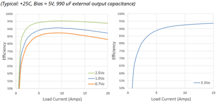
Efficiency versus load current for the POL-05-20S-T with a 5V input at 25°C, shown for 0.7V, 1.0V, and 2.5V outputs (left) and a 3.3V output (right). Image used courtesy of Microchip
Protection, Control, and Transient Behavior
Several features target high-current digital loads. True differential remote sensing compensates for up to 0.25V of drop along the current-carrying conductors. A droop function lowers the output voltage as load current climbs, limiting excursions during transients; the data sheet advises trimming the no-load voltage to the highest level the load can tolerate. Soft start ramps the output up in roughly 5 ms, an enable pin switches the unit, and an open-drain power-good flag reports when the output is within ±5% of its setpoint. Overvoltage and undervoltage protection pulls that flag low and lets the output sag without latching the converter off; it keeps attempting restarts until the fault clears.
Bench data fills in the loop picture. At a 5V input and 0.7V output, the data sheet shows 68° of phase margin, 22.5 dB of gain margin, and a crossover near 57 kHz, while a 10A-to-20A step at 1 A/µs produces a 50.4 mV peak-to-peak excursion. Those results used three 330 µF tantalum capacitors on the output. At least 330 µF is required, and the data sheet cautions that additional capacitance may be needed to avoid protection trips during load transients.
All told, the POL-05-20S-T gives spacecraft designers a compact, radiation-characterized way to power the core rails of FPGAs, microcontrollers, and ASICs. The 50W ceiling and the output capacitance requirement deserve attention early in a design, but a 20A module rated from −55°C to +100°C, sitting alongside Microchip’s EMI filters, DC-DC converters, and PIC64-HPSC computing devices, offers a handy foundation for processing-heavy space electronics, from newer commercial platforms to traditional missions.


